
Cycloidal (RV) vs. Precision Planetary Gearheads: Sizing Boundaries for Shock Loads, Tilting Moments, and BOM Cost
Compare cycloidal vs planetary gearheads for shock loads, tilting moments and duty cycles. Use the RFQ checklist to request a model-specific sizing review.
One-line decision: Shortlist cycloidal/RV reducers for demanding shock and moment loads, and precision planetary gearheads for compact servo transmission and demanding speed profiles. Select a model only after its torque-time envelope, output bearing limits, thermal duty and loaded accuracy all pass. Architecture alone does not establish an allowable shock multiplier or BOM saving.
Scope and engineering limits: This Global, English-language guide supports machine designers and procurement teams comparing precision gearheads for industrial automation. Published and technically reviewed: 27 October 2026. It provides a screening workflow, not a certified design, a measured endurance test or a price survey. Recheck when supplier specifications or application loads change. Supplier-specific curves and application approval govern final selection.
Fast action path: Start with the precision gearhead product portfolio, or request an engineering sizing review with your load-time profile, force offsets, target life and motor drawing.
Executive Summary: Compare the Complete Axis BOM
A reducer can pass nominal torque selection and still fail an axis requirement. An emergency stop introduces a short torque peak; an overhung fixture introduces a bending moment; a continuous traverse introduces a thermal load. These are separate checks.
For a lightly loaded fixture, an integrated robotic reducer may add cost without improving the required motion. For a heavy positioner, a cheaper shaft-output gearhead may require support bearings and a machined housing that erase its purchase-price advantage. Obtain quotes for both complete assemblies before choosing.
This comparison uses three primary references listed below, a model-level decision matrix and explicitly hypothetical calculations. It makes no universal claim about regional prices, lead times, efficiency or backlash drift.
1. Kinematics and Load Transfer: Tooth Loading vs. Distributed Contact
Precision Planetary Gearheads: Tooth Bending and Contact Stress
A planetary gearhead transmits torque from the sun gear through the planets to an output carrier within a ring gear. Tooth roots experience bending stress and the contacting flanks experience contact stress. Contact ratio, planet count, accuracy and load sharing affect capacity; a fixed count of loaded teeth cannot describe every spur or helical design.
The ISO 6336-1:2019 scope concerns load-capacity calculations for cylindrical involute gears. It does not certify a complete assembled gearbox, set a universal planetary shock limit or directly rate a cycloidal disc. Ask the supplier to check both repeated duty and rare overload events using the appropriate design method.
Cycloidal and RV Reducers: Multiple Lobe Contact Paths
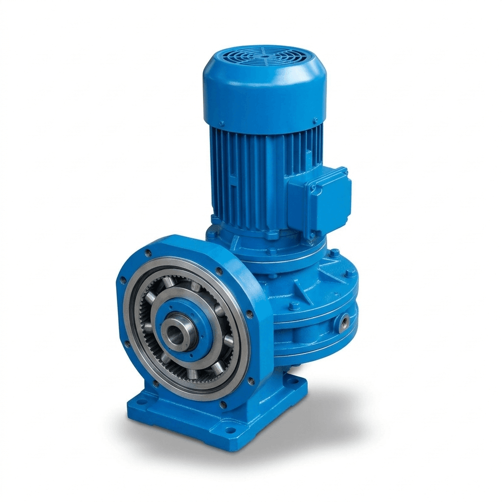
An eccentric mechanism drives a lobed disc against a pin ring. Multiple contact paths can distribute the load, but contact stresses, bearings, pins, shafts and lubrication remain limiting components. Some RV designs combine a primary gear stage with a cycloidal stage; the RV label should not be treated as the specification for every cycloidal reducer.
"Rolling compression" is a useful conceptual description, not proof of pure rolling, zero wear or immunity to failure. The schematic below illustrates load paths only; it is not a measured stress map or a rating chart.
For a bounded manufacturer example, Sumitomo advertises 500% shock-load capacity for its Cyclo 6000 gearmotor. That product-family statement is not a continuous torque allowance or a precision RV specification. Confirm duration, frequency and exclusions for the exact model. Do not infer that every planetary unit fails at the same load.
Torque screening: Express the load at the reducer output: T_out = J_out × alpha_out + T_process + T_friction + T_gravity, with inertia in kg·m², acceleration in rad/s² and torque in N·m. Use the signed time history, then check the supplier's repeated-duty method, acceleration/deceleration limit and emergency limit separately. A service factor must not be applied again to a peak that already includes the same shock allowance.
2. Tilting Moment and Bearing Span Architecture
Calculate the Moment at the Supplier's Bearing Datum
Tilting moment is distinct from torque about the output rotation axis. In general, calculate each force's moment vector from its offset and combine the vectors. For a conservative scalar screening case where the bending contributions act about the same axis and add:
M_k = F_r × (z + d_0) + F_a × y
Here F_r is radial force and F_a is axial force in newtons; z is the radial-force application distance from the mounting face, d_0 is the signed offset from that face to the supplier's bearing datum, and y is the axial-force radial offset, all in metres. Use the actual drawing datum. Opposing or perpendicular moments require the appropriate vector combination rather than this scalar sum.
Hypothetical worked example: Let F_r = 800 N, z + d_0 = 0.18 m, F_a = 1,200 N and y = 0.04 m. For the same-axis additive case, M_k = 800 × 0.18 + 1,200 × 0.04 = 192 N·m. This example excludes additional dynamic loads and is not a product rating. Submit the combined radial, axial and moment duty to the supplier for bearing life and static-load checks.
If an illustrative moment stiffness is 400 N·m/arcmin, this load alone produces 192 / 400 = 0.48 arcmin angular deflection. At a 200 mm tool radius, the small-angle displacement is approximately 200 × 0.48 × pi / 10,800 = 0.028 mm. This excludes torsional deflection, backlash, flange bending and fixture compliance. Use stiffness at the relevant operating point if the response is nonlinear.
Compare Bearing Systems, Not Only Gear Mechanisms
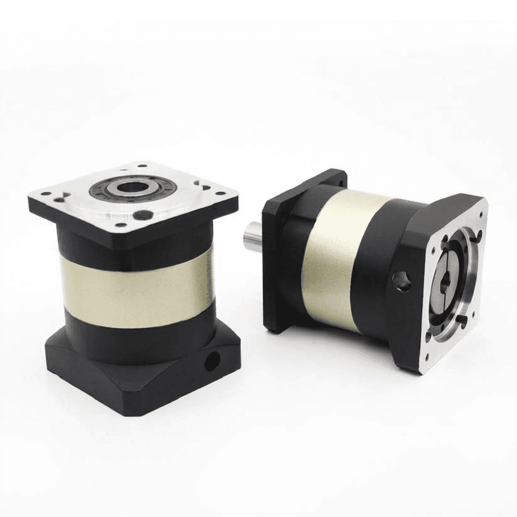
Shaft-output planetary units use different bearing arrangements; they are not all supported by closely spaced deep-groove bearings. Flange-output planetary and some RV reducers integrate larger output support bearings. Other reducers require external support. Confirm the actual bearing layout, allowable combined loads and housing stiffness.
The Nabtesco RV-E product data distinguishes torque, moment, thrust, speed, stiffness, backlash and lost motion. Those separate fields are the right RFQ structure. A high allowable moment does not by itself establish acceptable tool deflection, and bearing life must not be substituted for gear-train life.
3. Technical Comparison Matrix: Evidence Required Before Selection
These are screening tendencies, not interchangeable ratings. Compare candidate models at the required ratio, output speed and load spectrum.
| Engineering parameter | Precision planetary gearhead | Cycloidal / RV reducer | Procurement and sizing gate |
|---|---|---|---|
| Shock and emergency torque | Check tooth, shaft and coupling peak limits | Distributed contact can help; pins, bearings and any pre-stage still have limits | Obtain peak duration, permitted event count and repeated acceleration torque |
| Tilting moment and thrust | Output bearing design varies; flange versions may reduce external support needs | Some models integrate main bearings; others need external support | Verify combined loads at the specified datum and target life |
| Continuous input speed | Can suit demanding servo speeds; thermal limits remain model-specific | Continuous suitability depends on model, ratio and lubrication | Confirm continuous rather than peak speed at the actual ambient |
| Ratio and input inertia | Stage count and ratio affect speed, inertia and losses | A compound reducer may include a primary gear stage | Check actual ratio, reflected inertia and control response |
| Efficiency and heating | Depend on stage count, load, speed and lubricant | Depend on contact system, preload, speed and lubricant | Obtain an operating-point efficiency or loss estimate |
| Accuracy over service life | Backlash and stiffness classes require acceptance conditions | Lost motion and stiffness must be specified independently | Define initial and end-of-life limits; do not assume lifetime zero backlash |
| Centre aperture | Standard inline layouts may restrict routing; specialised designs differ | Hollow-bore versions exist, but not every RV model is hollow | Check usable bore, cable bend radius and rotary services |
| Complete installed BOM | Add support bearings, housings, adapters and assembly where needed | Integrated support may offset a higher reducer price | Compare dated, itemised assembly quotes on the same basis |
| Delivery and second source | Availability depends on configuration and region | Availability depends on configuration and region | Confirm lead time, interface compatibility and change-control terms |
4. Thermal Equilibrium and Continuous Duty
Both architectures produce heat from gearing, bearings, seals and lubricant movement. Nominal efficiency does not establish the temperature of a specific assembly. Continuous duty requires the selected reducer to reject its losses under the actual load, speed, mounting, orientation and ambient conditions.
Do not apply a universal 2,500 rpm cycloidal cutoff, a 5,000 rpm planetary allowance or a common casing temperature limit. Request the supplier's continuous speed/torque envelope and temperature measurement location. Motor duty labels such as S1 or S5 are useful context, but the reducer still needs its own thermal check.
For a validation sample, agree a representative cycle and worst expected ambient, monitor the specified temperature locations, and record when temperature stabilises. Check the result against the model's lubricant, bearing and seal limits. A short no-load run does not validate sustained production duty. Cooling or derating should follow the supplier's application guidance.
5. Application Boundaries: What to Shortlist
| Industrial axis | Main challenge | Candidate to evaluate first | Evidence needed before approval |
|---|---|---|---|
| Heavy welding positioner | Overhung fixture, shock and services routing | Integrated-bearing cycloidal/RV or supported planetary assembly | Combined moment/thrust, shock event count and usable bore |
| Rack-and-pinion gantry axis | Traverse speed and overhung pinion force | Planetary with suitable output bearings | Pinion force at its real offset, continuous speed and bearing life |
| Fast pick-and-place axis | Moving mass, reversals and settling | Compact planetary; compare alternatives where accuracy requires | Moving mass, reflected inertia, lost motion and measured settling |
| Stamping transfer feeder | Repeated impact and occasional jams | Shock-rated cycloidal/RV and appropriately protected planetary candidates | Measured or conservatively specified torque-time peaks and overload frequency |
| Rotary indexing table | Inertia, moment stiffness and cycle time | Flange-output planetary or cycloidal/RV | Acceleration torque, loaded accuracy and complete assembly BOM |
| Cable-routing rotary inspection axis | Central passage and positioning | Hollow-bore reducer or separately supported drive | Bore/service layout, cable life, moment capacity and loaded accuracy |
These shortlists do not approve an architecture. A missing load case or supplier rating keeps the selection open.
6. Sourcing and RFQ Decision Gate Checklist
Use the same requirements for each supplier so that lower price cannot hide an omitted load case.
- Gate 1 — Torque-time envelope: Include normal cycles, acceleration, braking, jams and emergency stops. Record peak magnitude, duration and lifetime event count; distinguish measured loads from assumptions.
- Gate 2 — Output support: Provide radial/axial force vectors, lever arms and a mounting drawing. Obtain combined-load bearing life, static capacity and allowable moment at the supplier's datum.
- Gate 3 — Thermal duty: State continuous and peak speeds, dwell times, mounting, ambient, orientation and lubricant. Request the approved thermal envelope and sample temperature test conditions.
- Gate 4 — Bore and interfaces: Freeze the motor, shaft/flange, pilot, bolt pattern, bore and cable-routing drawing revisions. A similar ratio or flange diameter does not establish interchangeability.
- Gate 5 — Loaded accuracy: Specify backlash, lost motion, torsional and moment stiffness separately, with test torque, temperature and tooling radius. Agree service-life acceptance conditions.
- Gate 6 — Installed cost and overload protection: Include supports, housing, adapters, assembly and inspection. Review the response time and limitations of torque limiters or drive limits; externally imposed impact may bypass motor-current limiting.
- Gate 7 — Delivery and change control: Obtain quantity-specific price, currency, Incoterm, warranty, spare availability and confirmed lead time. Qualify any second source against the same drawing and tests.
Send the completed RFQ checklist for engineering review before freezing the purchase specification.
7. Product Implementation and BOM Cost Boundaries
A flange-output planetary gearhead can be a useful candidate when its output support meets the moment and accuracy requirements. An RV assembly can be attractive when its integrated support or hollow-bore arrangement reduces other parts. Neither is automatically a drop-in replacement.
Hypothetical cost worksheet, USD per axis: The figures below are arithmetic inputs only, not PrecisionGearhead quotes, market averages or a claim that the two assemblies meet an actual application. Assume the same quantity, destination and acceptance specification; freight, duties, tax and lifecycle costs are excluded and must be added on the same basis.
| Cost item | Planetary assembly, USD | RV assembly, USD |
|---|---|---|
| Reducer | 600 | 1,100 |
| External support bearing | 180 | 0, assuming integrated support is adequate |
| Support housing / machining | 120 | 80 |
| Adapter and coupling | 90 | 90 |
| Assembly and inspection | 80 | 60 |
| Installed subtotal before excluded costs | 1,070 | 1,330 |
The reducer-only gap is USD 500; the assumed assembly gap is USD 260. If the planetary requires more support work, or the RV fails the thermal cycle, the result changes. Add maintenance, replacement labour and downtime only from an explicit service plan or disclosed risk assumptions; do not invent a failure rate to justify a preferred design.
Use the inline planetary gearhead range and high-torque planetary gearhead range to frame an inquiry. Request the exact model's ratings and interface drawing; the product photographs in this article illustrate geometry and are not evidence of tested shock capacity or lifetime accuracy.
8. Frequently Asked Questions
Do cycloidal reducers always handle more shock than planetary gearheads?
No. Distributed lobe contact can help carry overloads, but the selected model must meet the peak torque, duration and permitted event count. A momentary emergency rating is not a repeated acceleration rating, and no universal Ka threshold selects an architecture.
When is a flange-output planetary gearhead sufficient?
It is sufficient when the selected model meets the complete torque-speed duty cycle, combined radial and axial loads, tilting moment, bearing life and loaded accuracy requirements. Check the bearing arrangement and mounting stiffness before comparing its installed cost with an RV reducer.
What is tilting moment, and why can it limit gearhead selection?
Tilting moment is the bending moment created by forces acting at offsets from the output bearing datum. It can exceed bearing or stiffness limits while transmitted drive torque remains acceptable. Supply force directions, offsets and the load cycle with the RFQ.
Can a cycloidal or RV reducer run continuously?
Some models can. Confirm allowable continuous speed and thermal capacity at the actual ratio, load, ambient temperature, mounting and lubricant. There is no universal 2,500 rpm cutoff, and a peak speed rating does not establish continuous duty capability.
Does an RV reducer guarantee zero backlash for life?
No. Backlash, lost motion and torsional stiffness are different properties, and all depend on the model and measurement conditions. Agree an initial acceptance limit and a service-life limit at a defined test torque, temperature and cycle count.
How should procurement compare planetary and RV quotes?
Compare complete installed assemblies against the same load envelope and acceptance criteria. Include support bearings, housings, adapters, assembly, inspection, maintenance and landed delivery terms. Obtain dated quotes with quantity, currency, Incoterm and confirmed lead time; do not apply a generic price multiplier.
9. Sources and Engineering References
Sources checked 27 October 2026. Manufacturer statements below apply to their named products; they are not independent comparison tests or specifications for PrecisionGearhead products.
- ISO 6336-1:2019 — Calculation of load capacity of spur and helical gears, Part 1. The public abstract defines the involute-gear calculation scope and limitations. It does not validate this complete axis or a cycloidal load rating; no claim here relies on access to the paid standard text.
- Nabtesco Precision Equipment — RV-E product specifications. Model-level fields distinguish torque, moment, thrust, speed, stiffness, backlash and lost motion. Use the selected model and current supplier documentation rather than transferring a series headline to another size.
- Sumitomo Drive Technologies — Cyclo 6000 Gearmotor. This manufacturer page supports the named family's advertised 500% shock-load claim. It does not establish a universal cycloidal limit, precision class or overload duty for another reducer.
The worked moment, deflection and cost examples are disclosed calculations using assumed inputs. No customer case, hardware test result, market-price survey or lifetime wear measurement is asserted.
10. Next Steps: Secure the Axis Specification
Before requesting a final quotation, attach the torque-time profile, fixture mass and offsets, motor drawing, target life, loaded positioning tolerance and quantity plan. Ask suppliers to identify any unverified load case, propose a model and supply a written rating basis.
Contact PrecisionGearhead for an application review with that packet, or browse the product portfolio to identify candidate families. Freeze the interface drawing and sample acceptance plan before placing a production order.
Author

Categories
More Posts

Precision Gearhead Update 2026-W21: RFQ Gates After Tariff and Standards Signals
Precision gearhead and planetary gearhead decision brief for OEM and SI buyers: lock tariff, standards, inertia-ratio, and flange RFQ gates before PO rework.
IP65 vs IP69K Washdown Planetary Gearheads: Food-Grade Sourcing Guide
Compare IP65 vs IP69K washdown gearheads for food & beverage machinery. Learn the differences in sealing, stainless steel costs, and how to specify them in your OEM RFQ.
OEM Gearhead Lead-Time Planning: Prototype to Mass Production Without Schedule Drift
OEM lead-time control framework from prototype to MP, with stage gates, risk triggers, and recovery playbooks for schedule stability.