
Flange vs. Shaft Output Planetary Gearheads: Torsional Stiffness, Space, and Cost Trade-offs
Compare flange vs shaft output planetary gearheads for stiffness, space, and BOM cost. Use the checklist to choose the right OEM servo gearbox.
When specifying a precision planetary gearhead for an OEM motion control project, engineers and procurement teams often focus heavily on backlash, ratio, and frame size. However, one of the most critical mechanical architecture decisions is often overlooked until the design phase is well underway: the choice between a standard shaft output and a flange output.
The output configuration dictates how the mechanical power is transferred from the gearbox to the machine's load (a pinion, a pulley, a ball screw, or a rotary table). This single decision significantly impacts the system's torsional stiffness, its overall axial footprint, the assembly time on the factory floor, and the total Bill of Materials (BOM) cost.
For buyers, distributors, and design engineers navigating the sourcing of servo-driven precision gearheads, understanding when to pay the premium for a flange output—and when a standard shaft is actually the superior choice—is vital to protecting both margins and machine performance.
This guide provides a comprehensive technical and commercial breakdown of flange versus shaft output planetary gearheads, tailored for global B2B procurement and engineering teams.
Scope and Assumptions
- Last updated: July 22, 2026. Gearhead pricing, lead times, and coupling costs vary by supplier and region, so treat the cost example below as an RFQ model rather than a universal price list.
- Applies to: servo-driven precision planetary gearheads used in rack-and-pinion axes, rotary tables, compact gantries, AGV/AMR drive modules, and robot joints where output stiffness and bearing support affect positioning.
- Does not replace sizing: always verify peak torque, emergency-stop torque, radial and axial load, moment load, bearing life, backlash class, mounting tolerance, lubrication, and duty cycle against the supplier datasheet.
Executive Summary
- Shaft Output Gearheads are the industry standard. They utilize a smooth, keyed, or splined cylindrical shaft. They require a mechanical coupling to connect to the load, which introduces compliance but allows for slight misalignment. They are cost-effective and highly versatile.
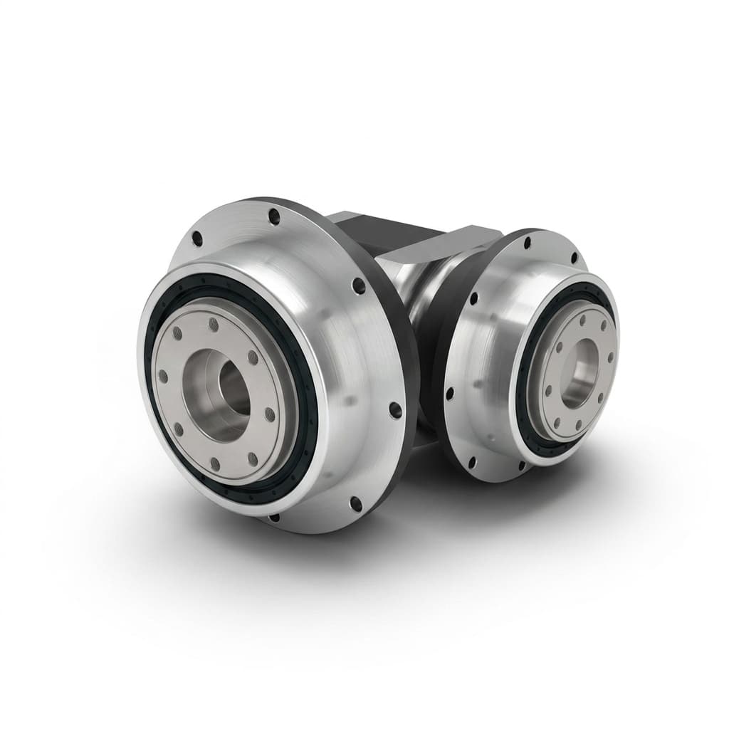
- Flange Output Gearheads feature a flat, disc-like interface (often conforming to the ISO 9409-1 standard) with threaded bolt holes and dowel pin sockets. The load is bolted directly to the gearhead. This eliminates the coupling, drastically increasing torsional stiffness and saving axial space.
- The Sourcing Reality: While a flange gearhead has a higher unit price, it eliminates the need to buy an expensive zero-backlash precision coupling. For rack and pinion systems, rotary index tables, and robotic joints, flange outputs often yield a lower total BOM cost and superior machine dynamics.
1. The Mechanical Distinction: Load Transfer Mechanisms
To evaluate the trade-offs, we must first look at how the mechanical power is physically transferred across the two designs.
The Shaft Output Model (The Traditional Approach)
A shaft output gearhead extends a solid steel cylinder outward from the gearbox housing. To transfer torque, an intermediate component must grip this shaft.
- Keyed Shafts: Use a square metal key sitting in a slot (keyway) to prevent the mating hub from slipping.
- Smooth Shafts: Rely on frictional clamping (e.g., a shrink disc or a compression coupling) to transmit torque without the stress concentrations of a keyway.
In almost all cases, connecting a shaft output gearhead to a driven load (like a ball screw) requires a coupling.
The Flange Output Model (The Direct Approach)
A flange output gearhead has no protruding shaft. Instead, the output carrier of the planetary gear stage is integrated directly into a heavy-duty rotary flange that sits flush with (or slightly recessed into) the front of the gearbox housing. This flange features a precisely machined centering pilot (a raised or recessed lip), threaded bolt holes, and typically one or more precision dowel pin holes. The load—such as a rack pinion or a rotary index plate—is bolted directly and rigidly to this face.
2. Torsional Stiffness and Machine Dynamics
In servo-driven automation, the goal is often high-speed positioning with minimal settling time. The enemy of fast settling times is "compliance" (the mechanical springiness of the system).
When a motor accelerates or decelerates a heavy load, any compliance in the driveline will cause the load to oscillate or "ring" before coming to a complete stop.
The Coupling Weakness
A shaft output requires a coupling. Even high-end, zero-backlash metal bellows couplings or elastomer jaw couplings act as torsion springs. They wind up under load and unwind when the load is removed. This torsional compliance significantly limits the control bandwidth of the servo drive. The tuning loop must be "detuned" (softened) to prevent resonance, resulting in slower machine cycle times.
The Flange Advantage
A flange output eliminates the intermediate coupling entirely. By bolting the load directly to the massive steel output carrier of the gearbox, the drive train approaches a rigid body.
- In a complete drive node, replacing a shaft-and-coupling stack with a direct flange connection can raise effective torsional stiffness by 50% to 100% in many servo-axis comparisons, but the exact gain depends on the coupling type, bolt preload, load inertia, and frame size.
- This extreme rigidity allows servo engineers to push the proportional and integral gains much higher in the drive amplifier, yielding aggressive acceleration profiles and near-instantaneous settling times.
3. Axial Space and Machine Footprint
In modern machine building, space is at a premium. Medical robots, automated guided vehicles (AGVs), and compact CNC gantries often struggle to fit the necessary actuators into the available envelope.
A shaft output gearhead requires space for the output shaft itself, the coupling, the coupling housing (bell housing), and the shaft of the driven load. This assembly can easily add 100mm to 200mm of dead axial length to the drive train.
Conversely, a flange output gearhead allows the load (e.g., a rack and pinion gear) to sit flush against the gearbox. The total actuator length is simply the length of the motor plus the length of the gearbox. For space-constrained OEM designs, this form-factor reduction alone justifies the flange gearhead.
4. Radial and Axial Load Capacity
Gearheads do not just transmit torque; they also act as structural supports for the driven load. Overhung loads (radial forces applied perpendicular to the shaft) and thrust loads (axial forces applied parallel to the shaft) exert immense stress on the internal bearings of the gearbox.
Shaft Overhung Loads
On a shaft output gearhead, the load (like a belt pulley) is mounted out on the shaft. This creates a lever arm. The further the load is from the gearbox housing, the higher the bending moment applied to the internal bearings. This reduces the permissible radial load rating and shortens bearing life.
Flange Bearing Architecture
Flange output gearheads are intrinsically designed to handle massive external forces.
- The flange is physically wider than a standard shaft, allowing the manufacturer to install much larger, high-capacity angular contact bearings or robust taper roller bearings right at the output face.
- Because the load is bolted flat against the flange, the lever arm is reduced to nearly zero. The bending moment is minimized.
- Result: In supplier comparisons, flange-output frame variants can often be rated for 2x to 3x higher radial and axial loads than shaft-output counterparts, but the actual margin depends on bearing package, mounting distance, speed, and required bearing life.
5. The Hidden BOM Cost Shift: A Procurement Perspective
If a buyer simply compares the unit price of a 90mm shaft output planetary gearhead to a 90mm flange output planetary gearhead, the shaft version will win every time. Flange gearheads require more complex machining, larger bearings, and more material. The premium is typically between 10% and 25%.
However, seasoned procurement teams understand that comparing bare gearhead prices is a flawed methodology. You must compare the installed cost of the entire drive node.
Cost Breakdown: Shaft Output Approach
- Planetary Gearhead (Shaft Output): $300
- Precision Zero-Backlash Coupling: $90
- Machined Bell Housing / Adapter Bracket: $50
- Assembly Labor (Aligning the coupling to prevent binding): $30 Total Node Cost: $470
Cost Breakdown: Flange Output Approach
- Planetary Gearhead (Flange Output): $360
- Precision Zero-Backlash Coupling: $0 (Not required)
- Machined Bell Housing: $0 (Not required, bolts direct)
- Assembly Labor (Simple bolt-on): $10 Total Node Cost: $370
By paying a $60 premium for the gearhead, procurement saves $100 in peripheral components and labor, yielding a net saving of $100 per axis while simultaneously improving the machine's mechanical performance.
6. Common Pitfalls: Fretting Corrosion and Keyway Failure
In applications with highly dynamic, reversing loads (such as delta robots or fast pick-and-place gantries), standard keyed shafts suffer from a chronic failure mode: fretting corrosion.
Even with a tight fit, violent torque reversals cause microscopic movements between the steel key and the keyway walls. Over thousands of cycles, this micro-friction rubs off tiny particles of steel, which immediately oxidize into red rust (fretting corrosion). Eventually, the keyway wall deforms, introducing severe mechanical backlash into the system that cannot be compensated for by the servo drive. The shaft is ruined.
Flange outputs bypass the keyed shaft/keyway failure path. The torque is transmitted through friction generated by the clamping force of multiple high-tensile bolts, supported by precisely reamed dowel pins for shear protection. A properly designed and torqued flange connection substantially reduces fretting-related backlash risk, but bolt preload, dowel fit, reversing torque, and service inspection still need to be validated.
7. Structured Comparison Matrix
Below is a technical and commercial reference table summarizing the trade-offs. Use this matrix during the design phase to align engineering specs with your procurement budget.
| Decision Parameter | Shaft Output Gearhead | Flange Output Gearhead |
|---|---|---|
| Mechanical Interface | Cylindrical shaft (smooth, keyed, or splined) | Flat rotary disc (ISO 9409-1 standard common) |
| Connection to Load | Requires intermediate coupling | Direct bolt-on integration |
| Torsional Stiffness | Moderate (limited by coupling compliance) | Extremely High (rigid body connection) |
| Axial Space Requirement | High (Gearbox + Coupling + Load Shaft) | Very Compact (Gearbox + Load) |
| Radial/Axial Load Capacity | Standard capacity (lever arm creates bending moments) | 2x to 3x higher capacity (larger bearings, zero lever arm) |
| Reversing Load Durability | Vulnerable to fretting corrosion on keyways | Lower keyway-fretting risk; bolted and dowel-supported connection |
| Base Unit Cost | Baseline Cost | 10% to 25% Premium |
| Total Assembly BOM Cost | Higher (must purchase precision couplings and brackets) | Often Lower (eliminates couplings and reduces labor) |
| Ideal Applications | Belt drives, general automation, distant load connections | Rack & pinion, rotary tables, robotic joints, direct drives |
8. Selection and Procurement Checklist
Before releasing an RFQ (Request for Quotation) for your next servo gearbox, use this checklist to confirm your output configuration is optimized:
- Are you driving a Rack and Pinion? If yes, default to a flange output. Bolting the pinion directly to the flange ensures the stiffness required for accurate linear positioning.
- Are you driving a Timing Belt? If yes, a shaft output is usually sufficient. The belt itself is highly compliant, so paying for the extreme torsional rigidity of a flange gearbox yields diminishing returns.
- Is the application highly reversing? (e.g., > 100 direction changes per minute). If yes, avoid keyed shafts to prevent fretting corrosion. Choose a flange output or a smooth shaft with a high-clamping-force shrink disc.
- Is axial space severely constrained? If you cannot fit a coupling in your machine frame, you must use a flange output.
- Is there high radial load (overhung load)? If the load acts heavily perpendicular to the gearhead (like a heavy wheel or index table), a flange gearhead with a larger output bearing package is usually the safer starting point.
- Does the supplier support ISO 9409-1? If specifying a flange, verify that the bolt circle diameter (BCD) and dowel pins match standard robotic interfaces for easier integration.
9. Application Boundaries: When a Shaft Output is Actually Better
Despite the advantages of the flange output, it is not a universal solution. There is one major scenario where a shaft and coupling are mechanically superior: Misalignment Compensation.
A flange output is a rigid connection. It assumes the mating machine frame is perfectly machined. If you are connecting the gearhead to a load that is supported by its own external bearings (for example, a long ball screw supported by pillow blocks at both ends), any slight angular or parallel misalignment between the gearbox and the ball screw will result in massive binding forces. These forces will rapidly destroy the bearings in both the gearhead and the ball screw.
In this scenario, a shaft output with a flexible coupling (like an elastomer jaw coupling) is usually the safer choice. The coupling acts as a mechanical fuse, flexing to absorb the misalignment and protecting the expensive bearings.
Related Engineering Guides
- Backlash vs. repeatability: how to set acceptance criteria before PO
- Helical vs. spur planetary gearheads: noise, cost, and torque trade-offs
- RFQ checklist for planetary gearhead OEM projects
Sources and Last Verified
- ISO 9409-1:2004 - Manipulating industrial robots — Mechanical interfaces — Part 1: Plates
- AGMA 9005-F16 - Industrial Gear Lubrication and Power Transmission Guidelines
- Neugart Wiki - Gearbox and application engineering reference
- R+W America - Bellows coupling basics
These engineering standards, gearhead references, and coupling-design publications support the principles of mechanical interfaces, lubrication context, torsional rigidity, and coupling compliance. BOM cost examples are illustrative and vary by supplier and region.
Last verified: July 22, 2026.
Request a Sourcing Consultation
Unsure if your next machine generation should transition from shaft outputs to flange outputs? The calculation involves more than just unit price—it requires a complete review of your load profile, dynamic settling requirements, and assembly labor.
Let our engineering team run the calculations for you. We provide detailed sizing reports, including radial load life-expectancy and torsional wind-up estimates.
Email your current BOM and load requirements to [email protected] or reach out via WhatsApp at +8618857971991.
You can also explore our product catalog or read more engineering sourcing guides to refine your specifications before submitting an RFQ.
Author

Categories
More Posts
RFQ Checklist for Planetary Gearhead OEM Projects: From Drawing to Pilot Lot
RFQ gate framework for planetary gearhead OEM programs, covering boundary definition, acceptance methods, quote comparability, and release logic.

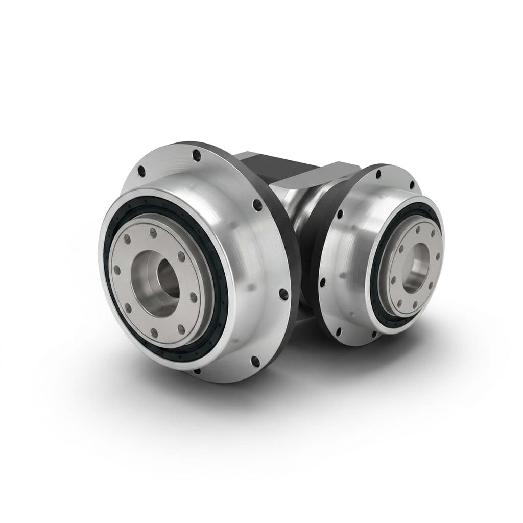
Helical vs Spur Planetary Gearheads: Noise, Torque, and Cost Trade-offs
Compare helical vs spur planetary gearheads for noise, torque density, axial-thrust risk, efficiency, cost, and RFQ decisions in OEM sourcing.
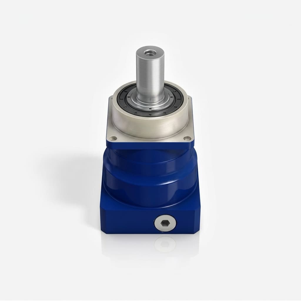
Backlash vs Repeatability: How to Set Acceptance Criteria Before PO
Buyer-side method to separate backlash and repeatability, lock test protocols, and release PO with measurable acceptance evidence.