
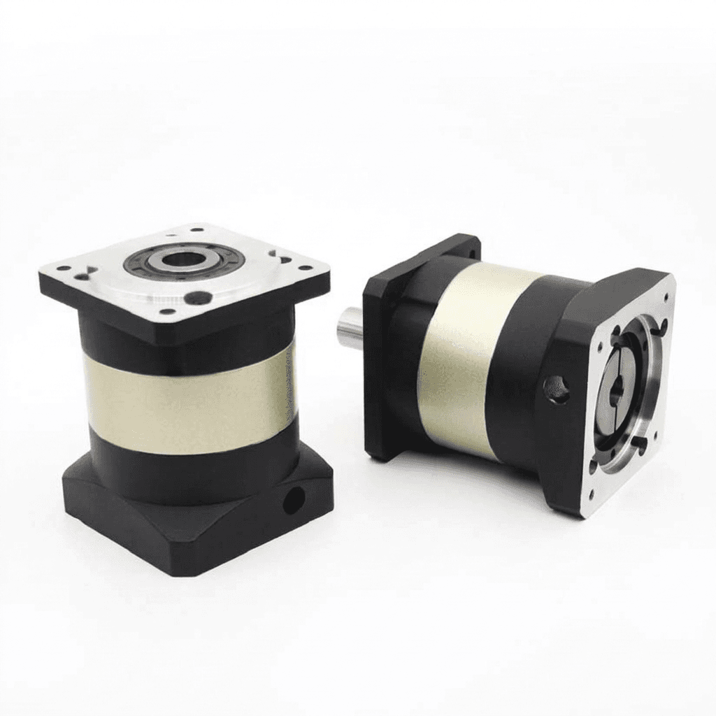
Rack and Pinion Planetary Gearheads: Cantilevered Sizing, Radial Moments, and Backlash Preload for Gantry Axes
Size rack and pinion planetary gearheads for gantries. Compare bearing loads, pinion supports, and backlash preload; prepare an RFQ with our checklist.
One-line decision: Size rack and pinion planetary gearheads for output torque, combined bearing loads, and loaded positioning error together. A shorter pinion overhang can improve bearing loading; preload addresses reversal clearance. Neither substitutes for the other.
Scope and review date: Reviewed 6 November 2026 for mechanical engineers and procurement teams selecting horizontal industrial gantry axes worldwide. The calculations below are an illustrative engineering screen, not measured machine performance or a product rating. Vertical lifting, personnel handling, safety braking, shock loading, and contaminated environments require additional application-specific assessment.
Fast action path: Compare high-torque planetary gearheads and inline planetary gearheads, then send an engineering RFQ with your load cycle, pinion geometry, and support drawing. Ask for a combined-load calculation rather than approval from torque alone.
Executive Summary: The Rack-and-Pinion Precision Bottleneck in Gantry Automation
Long-travel Cartesian gantries often use rack-and-pinion drives because modular racks can extend along a machine bed without a long rotating screw. Ball screws and linear motors remain alternatives; travel length alone does not decide among them. Required speed, critical screw speed, structural stiffness, contamination, control capability, and installed cost determine the useful comparison.
A rack drive introduces a selection problem that a gearbox torque check can miss: the pinion applies loads directly to the output support. A reducer that provides adequate acceleration torque may still have insufficient bearing capacity or excessive mesh deflection at the actual pinion offset.
Start with four separate questions:
- What force must each drive deliver during acceleration, cutting, deceleration, and emergency stopping?
- What torque, radial load, axial thrust, and bending moment reach the output support?
- Does the selected bearing arrangement meet peak-load, fatigue-life, and stiffness requirements?
- How much reversal lost motion and loaded positioning error can the process tolerate?
Calculate pinion output torque as T_out = F_t * d_0 / 2, using pitch diameter in meters. For reduction ratio i = motor speed / output speed and motoring efficiency eta, the load-related motor torque is approximately T_motor = T_out / (i * eta). Include motor and drivetrain acceleration torque separately. Dividing by ratio gives an input-side estimate, not the gearbox output torque requirement.
1. Helical Tooth Engagement: Tangential, Separating, and Axial Forces
Helical teeth provide overlapping engagement but also generate thrust along the pinion shaft. Spur teeth avoid that helix-induced thrust; they still generate tangential and radial separating forces. Neither tooth form removes the need to calculate bearing loading.
For a helical pair described by normal module m_n, normal pressure angle alpha_n, helix angle beta, and pinion tooth count z, use the following relationships. Angles and module conventions must match the supplier drawing; substituting transverse pressure angle into the normal-angle expression gives an incorrect separating force.
Pitch diameter:             d_0 = m_n * z / cos(beta)
Output torque:              T_out = F_t * d_0 / 2
Radial separating force:    F_r = F_t * tan(alpha_n) / cos(beta)
Axial thrust magnitude:     F_a = F_t * tan(beta)
Shaft-transverse resultant: F_perp = sqrt(F_t^2 + F_r^2)
Use consistent length units when converting force into torque. Here, “radial separating force” describes the mesh direction; the gearbox bearing's radial loading also includes the tangential feed force, because both act perpendicular to its shaft. Helix hand and drive direction determine the thrust sign. Check both acceleration and braking directions rather than assigning one favorable thrust direction throughout the duty cycle.
The ATLANTA servo drive catalog, in its rack-and-pinion selection sections, provides manufacturer-specific geometry and load-selection data. Select the actual rack/pinion combination before applying its ratings.
Numerical Sizing Walkthrough: An Illustrative Gantry
This example uses assumed inputs to expose the load paths. It is not a customer case study, a test record, or approval for a particular gearbox.
- Moving bridge mass:
m = 1,200 kg. - Horizontal acceleration:
a = 15 m/s^2. - Illustrative guide friction coefficient:
mu = 0.005. - No cutting force, cable drag, process thrust, or preload is included in this initial calculation.
- Two opposite-side gantry drives are assumed to share force equally.
Acceleration force is 1,200 * 15 = 18,000 N. Estimated friction is 1,200 * 9.81 * 0.005 = 58.9 N. Total feed demand is therefore approximately 18,059 N, or 9,030 N per drive after rounding. Actual sharing depends on payload position, bridge stiffness, synchronization, and disturbances; an off-center payload may invalidate the equal-share assumption.
For m_n = 3 mm, z = 20, alpha_n = 20 degrees, and beta = 19 degrees 31 minutes 42 seconds:
cos(beta) = 0.942476; tan(beta) = 0.354675
Pitch diameter d_0 = 63.662 mm; pitch radius r_0 = 0.031831 m
T_out  = 9,030 * 0.031831                  = 287.4 N·m
F_r    = 9,030 * tan(20 degrees)/0.942476  = 3,487 N
F_a    = 9,030 * 0.354675                  = 3,203 N
F_perp = sqrt(9,030^2 + 3,487^2)           = 9,680 N
These are peak demands for the assumed operating point. Continuous torque, output speed, tooth strength, emergency stopping, and any preload forces remain separate checks. Two drives on opposite sides of a gantry do not automatically form an anti-backlash pair: electronic preload normally needs opposed pinion forces on the same rack or another specifically engineered force path.
2. Cantilevered Pinion vs. Outboard Bearing Support vs. Flange Output
A shaft-mounted pinion needs space for its hub, retaining hardware, shoulder, and seal clearance. The critical load offset x runs from the effective front bearing reaction plane to the pinion face center. A drawing dimension from the housing face is useful, but the supplier must add the internal distance to the bearing plane.
A flange output can shorten this offset and provide a different bearing arrangement. The ATLANTA HighForce systems page documents flange and outboard-supported configurations. Compare actual load envelopes; a flange interface does not make the offset or bearing load vanish. An outboard support also changes the constraint system and needs alignment and thermal-expansion provisions.
Combined Bending Moment: Include Both Transverse Forces
Tangential force produces bending F_t * x as well as drive torque F_t * r_0. Separating force produces bending in the orthogonal plane. Axial thrust applied at pitch radius introduces an additional bending couple in that second plane. For an idealized centered contact point, a conservative combination is:
M_t_plane = F_t * x
M_r_plane = F_r * x + F_a * r_0
M_b,worst = sqrt(M_t_plane^2 + M_r_plane^2)

At x = 0.045 m:
M_t_plane = 9,030 * 0.045                     = 406.4 N·m
M_r_plane = 3,487 * 0.045 + 3,203 * 0.031831   = 258.9 N·m
M_b,worst = sqrt(406.4^2 + 258.9^2)            = 481.8 N·m
The thrust couple can add to or subtract from the separating-force moment depending on helix hand and direction; the expression above uses the additive case. Evaluate the signed load vectors for the actual assembly. The 258.9 N·m second-plane value alone is not the total bending demand. Torsion 287.4 N·m remains a separate component; do not add it arithmetically to bending or compare it to a moment rating defined at a different reference plane.
Shaft Deflection and Tooth Contact
Bearing survival alone is insufficient. Shaft bending, bearing compliance, mounting plate flexibility, rack alignment, and thermal movement all affect face contact. A small angular mismatch can concentrate contact near an edge, but there is no universal 1.5-arcminute limit or failure-hour prediction for every rack. Face width, crowning, load, and tooth geometry change the permissible misalignment.
Request the supplier's loaded shaft tilt or stiffness data and permissible mesh alignment. Verify the assembled contact pattern at a representative load and inspect reversal behavior at the process speed. Do not interpret a no-load backlash certificate as proof of adequate loaded tooth contact.
3. Bearing Fatigue Life Under Combined Loads
For a simplified two-support shaft, take bearing span a = 0.060 m. The following reaction magnitudes use the same additive thrust-couple case. Rear and front transverse reactions act in opposite directions in each bending plane; actual bearing geometry and internal gearbox forces require the supplier's model.
Tangential plane:
R_front,t = F_t * (1 + x/a) = 15,803 N
R_rear,t  = F_t * x/a       =  6,773 N

Separating plane, additive thrust-couple case:
R_front,r = F_r * (1 + x/a) + F_a*r_0/a = 7,802 N
R_rear,r  = F_r * x/a + F_a*r_0/a       = 4,315 N

Resultant external-load radial reactions:
R_front = sqrt(R_front,t^2 + R_front,r^2) = 17,623 N
R_rear  = sqrt(R_rear,t^2 + R_rear,r^2)   =  8,030 N
These radial reactions do not include axial load sharing, installed preload, or internal planetary mesh loads. They are not the equivalent bearing loads P used directly in a life calculation. Their practical purpose is to show why considering only the 3,487 N mesh separating force is inadequate.
The ISO 281 Life Relationship and Its Limits
The SKF super-precision bearing catalog, printed pages 33–35, explains equivalent load and basic rating life:
L10h = 1,000,000 / (60*n) * (C/P)^p
p = 3 for ball bearings; p = 10/3 for roller bearings
Here C is dynamic rating, P is the bearing-specific equivalent dynamic load, and n is constant rotational speed in rpm. L10 represents 90% statistical reliability under the model assumptions, not guaranteed service life. Combined radial and axial loading needs the selected bearing's factors and arrangement; preload and lubrication also matter.
As an arithmetic sensitivity example, increasing an already-established P by 40% reduces calculated life to 1/1.4^3 = 36% for balls or 1/1.4^(10/3) = 33% for rollers, with other inputs fixed. This is not a predicted field failure time.
For variable operation, derive each segment's bearing load first. Weight fatigue exposure by revolutions, not merely elapsed time; SKF discusses variable conditions on printed page 35. Standstill and short oscillations need separate checks.
4. Backlash Preload: Mechanical Split-Pinion vs. Dual-Motor Electronic Control
Gearbox angular backlash and rack-to-pinion flank clearance are different contributors to reversal lost motion. Elastic shaft twist, bearing tilt, structure deflection, thermal drift, and pitch error add further positioning effects under load.
Convert gearbox backlash to a rack displacement at pitch radius:
s_backlash = (j_rotary/60) * (pi/180) * (d_0/2)

For j_rotary = 3 arcmin and d_0 = 63.662 mm:
s_backlash = 0.0278 mm = 27.8 micrometers
If the selected mesh has an independently established linear reversal clearance of 40 micrometers, a simple rigid-path budget gives approximately 68 micrometers before compliance and other effects. That clearance is an assumed example input, not a standard value for all module-3 racks. Confirm how each supplier measures backlash, including torque, temperature, mounting, and reference point.
Preload maintains contact on opposing flanks. A split-pinion generally uses a spring or adjusted mechanical bias; a dual-motor system commands opposing torques. Both have finite preload capacity. Excess external load can unload one flank, and excessive preload increases contact loads and thermal demand. A mechanical split-pinion driven through one reducer does not automatically remove that reducer's internal backlash.
Table 1: Backlash Strategies and Procurement Trade-offs
The six rows compare architectures qualitatively. They are not measured cost multiples or universal accuracy ratings.
| Architecture | Main benefit | Remaining limitation | Control requirement | Evidence to request |
|---|---|---|---|---|
| Standard low-backlash single drive | Simple integration and fewer components | Gearbox play and mesh clearance remain | One servo axis | Backlash test conditions and loaded reversal result |
| Precision flange-output single drive | Potentially shorter offset and stiffer support | Flange geometry alone does not remove mesh clearance | One servo axis | Combined-load envelope and output stiffness |
| Mechanical split-pinion | Opposing flanks can remain engaged within preload capacity | Spring compliance, wear, and reducer play remain | Usually one servo axis | Preload capacity and maintenance adjustment method |
| Mechanically linked dual pinions | Mechanical bias across separate contact points | Coupling compliance and assembly adjustment | One drive with a designed mechanical link | Torsion setting, load distribution, and reversal test |
| Dual motors with constant torque bias | Controlled opposing contact through reversals | Persistent bias adds motor and tooth loading | Coordinated drives and fault handling | Per-motor current, temperature, and stopping behavior |
| Dual motors with scheduled torque bias | Bias can vary with process demand | Reduced bias can permit lost motion during transitions | Validated coordinated torque scheduling | Transition following error and measured loaded repeatability |
For a common symmetric bias convention, the two output torques may be written T_1 = T_axis/2 + T_bias and T_2 = T_axis/2 - T_bias. This is a bookkeeping example, not a universal control law. If the process requires opposite torque signs at all times, the chosen bias must maintain that condition across the operating range while respecting each drive's limits. Check each gearbox against its own torque and mesh-force history, including regenerative operation.
ATLANTA's HighForce documentation describes electronic master/slave preloading and operating modes where the pinions drive together. Those modes require suitable controls; they do not establish zero total positioning error. Releasing bias for a traverse can reintroduce clearance, so validate the transition before the next precision cut.
If you are comparing these options, request a support-and-preload review with the desired reversal tolerance, maximum process force, and controller capability. This helps distinguish a mechanical support problem from a control or clearance problem before changing the BOM.
5. Rack Accuracy Grades and the Axis Error Budget
A low-backlash gearhead cannot correct a rack whose pitch or mounting error already exceeds the machine error budget. Ask for the exact supplier grade definition and referenced standard edition, rather than treating labels such as “DIN 6” as complete specifications.
A quality class is not a universal material, hardening process, speed limit, dynamic factor, or price band. The ATLANTA rack range lists multiple manufacturing and treatment options and identifies conditions behind its load ratings. ISO 1328-1 terminology for cylindrical gear flank tolerances should not be treated as a complete rack acceptance specification without the supplier's stated applicability and inspection method.
Table 2: Six Rack Acceptance Questions
| Characteristic | What to put in the RFQ | Why it affects the decision |
|---|---|---|
| Single pitch deviation | Supplier limit, module, and inspection method | Local mesh disturbance and incremental position error |
| Cumulative pitch deviation | Limit over a stated inspection length and temperature | Travel accuracy over a rack section |
| Rack joint alignment | Joint pitch and mounting procedure | Local following error when crossing segments |
| Tooth geometry | Normal module, pressure angle, helix hand, face width | Compatible engagement, thrust, and tooth capacity |
| Material and treatment | Material specification, hardness, and depth where required | Strength, wear behavior, and finishing suitability |
| Mounted straightness and parallelism | Datum, assembled tolerance, and measurement method | Contact pattern, binding risk, and error after installation |
Do not multiply a section's inspection limit by the number of sections and call the result a measured full-axis error. Joint errors, mounting, temperature, and compensation change the result. Measure assembled travel under agreed conditions, and distinguish absolute accuracy from repeatability.
As an error-budget example, a process allowing 50 micrometers total reversal-related displacement cannot allocate all of it to a gearbox contributing 27.8 micrometers; the rack clearance and load-dependent terms need room too. Pitch accuracy and thermal drift may need separate acceptance tests, especially over long travel. Linear feedback or compensation can address some systematic errors, but neither repairs an overloaded bearing or poor tooth contact.
6. Peak Loads, Duty Cycles, and Sizing Boundaries
A duty label such as S1 or S5 does not replace a motion profile. S5 describes intermittent periodic motor duty including starting and electric braking; motor duty terminology alone does not establish the reducer's bearing life or thermal rating. Give suppliers segment durations, output speed, torque direction, process force, preload, ambient conditions, and emergency-stop requirements.
For example, a motion cycle could contain 0.15 s acceleration, 0.8 s constant-speed travel, 0.15 s braking, and 0.2 s rest. Acceleration and braking speed vary throughout those segments. Use sufficient subdivisions or integration for fatigue exposure; time-averaging moment alone misses the changing speed and the actual bearing load path.
For bearing load segments P_i, speed magnitudes n_i, and durations t_i, an equivalent-load screen is:
P_eq = [sum(P_i^p * abs(n_i) * t_i) / sum(abs(n_i) * t_i)]^(1/p)
n_mean = sum(abs(n_i) * t_i) / sum(t_i)
Use compatible units and sufficiently resolved segments. A single P_eq assumes a consistent bearing life model; changing lubrication, temperature, and contact conditions can require segment damage calculations instead. Zero-speed intervals contribute no revolutions in this expression but still require static-load, lubrication, and fretting assessment.
Table 3: Six Independent Release Checks
Module alone cannot establish maximum feed force, permissible overhang, or allowable acceleration. Use these checks against the selected component drawings and ratings.
| Release check | Required input | Acceptance evidence |
|---|---|---|
| Tooth capacity | Rack/pinion material, geometry, duty, and lubrication | Supplier tooth bending and contact-load assessment |
| Peak torque and bending | Worst direction, stop profile, and actual offset | Combined-load envelope at the stated reference plane |
| Static bearing capacity | Peak reactions and axial load distribution | Bearing static safety calculation with supplier factors |
| Dynamic bearing life | Bearing loads, ratings, speed history, and reliability target | Documented life calculation and assumptions |
| Thermal duty | Motor currents, output losses, preload, and ambient | Approved continuous operating limits or thermal test |
| Loaded positioning | Backlash, compliance, alignment, feedback, and process force | Agreed reversal, contact-pattern, and travel tests |
Bearing static safety is commonly expressed through static rating and equivalent static load, s_0 = C_0/P_0, using the bearing manufacturer's method. A gearbox's permissible moment is not automatically a bearing static rating, and a ratio of moment limits is not a universal brinelling criterion. Ask the gearbox supplier to reconcile simultaneous loads rather than checking each catalog maximum in isolation.
7. Sourcing and Engineering RFQ Checklist
Before releasing a production purchase order, send a consistent input package to competing suppliers. Otherwise one quotation may include a shorter pinion hub or different preload assumption and appear better simply because its load case is easier.
- Define the force history: moving mass, acceleration, process force, friction estimate, cable drag, load sharing, and stopping cases. Identify every assumed value.
- Dimension the support geometry: pinion center, housing datum, shaft extension, and any outboard bearing. Ask the supplier to identify effective bearing planes and span.
- Request combined-load verification: output torque, both transverse forces, thrust, bending moments, stiffness, and bearing life for the exact reducer configuration.
- Allocate positioning error: specify gearbox backlash measurement conditions, rack clearance, loaded reversal tolerance, and the process measurement point.
- Specify rack acceptance: supplier grade definition, pitch inspection length, material/treatment, joint procedure, and assembled alignment criteria.
- Define lubrication and environment: lubricant compatibility, delivery method, contamination protection, temperature range, and maintenance interval. Automatic lubrication is an option to evaluate, not a substitute for the rack supplier's requirements.
- Check integration and control: motor interface, hub retention, input speed, inertia, preload scheduling, fault response, and acceptance-test records. Keep preliminary sizing approval separate from final machine acceptance.
For inertia screening, use our inertia matching calculator. It supports a different part of motor selection; it does not validate tooth strength, combined bearing loads, or the preload control design.
8. Frequently Asked Questions
Why can a cantilevered pinion overload a planetary gearhead that meets the torque requirement?
Torque capacity does not establish output bearing capacity. Tangential feed force and radial separating force both bend an overhung shaft, while helical axial thrust adds an eccentric moment. Check their combined bearing reactions, thrust load, and shaft deflection against the selected assembly ratings.
How do you calculate the radial separating force and axial thrust on a helical rack?
For normal pressure angle alpha_n and helix angle beta, use F_r = F_t * tan(alpha_n) / cos(beta) and F_a = F_t * tan(beta). At alpha_n = 20 degrees and beta = 19.5283 degrees, these are approximately 0.3862 * F_t and 0.3547 * F_t. The bearing radial load also includes the tangential force F_t.
What is the maximum acceptable shaft deflection angle for rack and pinion meshing?
There is no universal arcminute limit. Obtain the permissible mesh misalignment from the rack and pinion supplier, then include shaft bending, bearing compliance, mounting error, and gantry deformation. Verify tooth contact under the agreed representative load.
When should an OEM choose an ISO 9409-1 flange output gearhead over a shaft output?
Consider a flange output when its shorter load offset and specified bearing stiffness improve the combined-load calculation or packaging. ISO 9409-1 describes the mechanical interface; it does not certify moment capacity, backlash, or service life. No single feed-force or acceleration threshold selects the architecture.
What is the difference between mechanical split-pinions and dual-motor electronic preloading?
A mechanical split-pinion uses opposed, preloaded tooth halves with one drive. Electronic preload uses two controlled motor and gearbox sets to maintain opposing tooth contact. Either can reduce reversal clearance while preload remains effective, but neither eliminates elastic deflection, rack pitch error, or all positioning error.
How does rack pitch error affect gearhead selection and machine accuracy?
Low gearbox backlash cannot correct rack pitch error. Specify the rack supplier quality definition, inspection length, pitch deviations, material, and mounting conditions separately. Allocate an axis error budget and verify the assembled travel; a quality grade alone does not establish speed capability or positioning accuracy.
How does an outboard bearing bracket compare to a flange-mounted planetary gearhead?
An outboard bearing can redistribute pinion bending loads when the shaft, housing, and support are designed together. It adds alignment and thermal expansion constraints and does not remove all gearbox loads. A flange output can reduce overhang in a compact assembly; compare documented stiffness and combined-load capacity for both options.
9. Sources and Engineering References
Sources checked for this review on 6 November 2026. Manufacturer ratings apply to their specified products and conditions. The numerical example, reaction calculations, and comparison tables above are illustrative analysis, not independent product tests.
- ATLANTA Servo Drive Systems Catalog: See the rack-and-pinion drive calculations and selection sections for geometry and product-specific selection data. This does not establish universal load limits by module.
- ATLANTA HighForce Planetary Rack & Pinion Drive Systems: Documents flange-output, supported-pinion, and electronically preloaded configurations, with product-specific ratings.
- ATLANTA Gear Racks: Describes rack construction options and qualifications behind feed-force ratings, including pinion and lubrication assumptions and service factors.
- SKF Super-precision Bearings, PUB BU/P1 13383/2 EN: Printed pages 33–35 cover equivalent dynamic load, ISO 281 basic rating life, and variable operating conditions. Use the selected bearing's own chapter for arrangement-specific load factors.
10. Engineering Sizing Support
A release-ready gantry selection needs an agreed load case, component-specific combined-load evidence, and a measured positioning acceptance plan. Shortening overhang can reduce bending, while appropriate preload can reduce reversal clearance within its working range. Neither guarantees a fixed operating life or removes every source of axis error.
Compare high-torque planetary gearheads and inline planetary gearheads against your installation envelope. To request an engineering drawing review, send the moving mass, motion profile, rack/pinion specification, support dimensions, positioning target, controller details, and intended service life. Ask the quotation to identify unverified inputs and the tests needed before production approval.
Author

Categories
More Posts
Backlash vs Repeatability: How to Set Acceptance Criteria Before PO
Buyer-side method to separate backlash and repeatability, lock test protocols, and release PO with measurable acceptance evidence.

AGV/AMR Wheel Drive Gearheads: Radial Load Constraints and Bearing Life Sourcing Guide
How to specify and source precision gearheads for Automated Guided Vehicles (AGVs) and Autonomous Mobile Robots (AMRs) to prevent premature flange bearing failures.
Precision Gearhead Update 2026-W25: Inertia Matching & Sourcing Controls
Weekly precision gearhead update: lock rotor-to-load inertia ratio limits, check standards, and freeze motor-to-gearhead flange interface drawings at RFQ.