
Cleanroom and Vacuum Planetary Gearheads: Outgassing, PFPE Lubrication, Particle Emission Classes, and Semiconductor Sourcing
Select cleanroom and vacuum planetary gearheads with outgassing evidence, PFPE lubrication limits, particle testing, and a semiconductor RFQ checklist.
One-line decision: Select cleanroom and vacuum planetary gearheads against three separate acceptance criteria: airborne particle release, molecular contamination, and mechanical performance at the actual pressure and duty cycle. A grease label or room classification cannot approve the complete drivetrain.
Scope and review date: Reviewed 12 November 2026 for semiconductor equipment engineers, wafer-handling integrators, and procurement teams worldwide. This English-language guide covers atmospheric cleanroom installations and preliminary screening for in-chamber motion, including applications targeting 10⁻⁶ mbar. It does not qualify equipment for EUV optics, reactive process gases, sterile processing, or ultra-high vacuum; those require process-specific review.
Fast action path: Compare precision inline planetary gearheads, review the OEM engineering process, or submit an engineering RFQ with installation location, pressure, temperatures, and motion duty. Ask which requested features and qualification records are available before selecting a configuration.
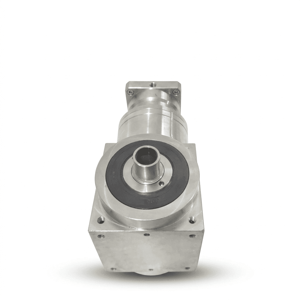
Evidence boundary: This is a standards-informed selection framework, not a report of tested PrecisionGearhead hardware. The diagrams are explanatory illustrations; the calculation below uses assumed inputs. No product particle certificate, customer yield result, or supplier-specific vacuum rating is established here. The header photograph shows a housing example and is not evidence of vacuum qualification.
1. Executive Summary: Separate the Three Contamination Questions
A planetary gearhead can satisfy positioning and torque requirements while remaining unsuitable for its installed environment. Wear debris from a shaft seal, lubricant migrating toward a wafer, and gas released during pump-down are different failure mechanisms. They need different measurements and controls.
Start by locating the gearbox relative to the process boundary. An actuator outside the chamber, connected through an approved rotary feedthrough, faces different requirements from a lubricated gearhead next to the workpiece in vacuum. An atmospheric cleanroom assembly behind an extraction enclosure also differs from an exposed axis directly above a wafer path. Moving the gearbox away from the sensitive zone may be more practical than qualifying every internal component for direct exposure.
Keep these three decisions explicit:
- Particle release: What airborne or deposited particle contribution is allowed during acceleration, reversal, and steady motion? State particle sizes, sampling positions, and background conditions.
- Molecular contamination: Which volatile species or deposits are unacceptable near the substrate, optics, or sensors? Define material screening separately from chamber-level cleanliness.
- Mechanical capability: Can the selected lubricant, bearings, seals, and heat path support the load spectrum at pressure? A catalog rating needs confirmation when those conditions change.
The useful purchasing question is therefore: “What evidence supports this exact configuration in this operating envelope?” A broad claim of “cleanroom compatible” leaves too many acceptance conditions undefined.
Figure 1. Original selection workflow. No pressure curve, emission rate, or service life is implied.
2. Outgassing Physics and ASTM E595: What the Evidence Covers
ASTM E595 is a material outgassing test method, not a semiconductor gearbox certification. Its familiar test exposure is 125°C for 24 hours under specified vacuum conditions, with a cooler collector. Request the controlled method edition, sample preparation, temperatures, pressure, and actual report from the laboratory.
The reported quantities include total mass loss (TML), collected volatile condensable material (CVCM), and water vapor regained (WVR). TML describes specimen mass lost; CVCM describes material collected as condensate relative to initial specimen mass; WVR records moisture regained after conditioning. The NASA Goddard outgassing database provides material-screening records using this method. A matching trade name alone does not establish identical preparation or formulation.
You may encounter screening limits of 1.0% TML and 0.10% CVCM in procurement specifications. Treat these as explicitly agreed screening criteria, not limits imposed by E595 on every semiconductor tool. Passing them cannot establish acceptable deposition on a sensitive optic or the operating pressure of an assembled gearbox.
Separate three pieces of evidence in the RFQ: the lubricant material report, the bill of materials and cleaning record, and the assembled-unit vacuum test. Where required by the process owner, add residual gas analysis or a contamination witness near the relevant surface. Specify temperature and motion because a stationary, room-temperature sample does not represent a warm axis repeatedly accelerating under load.
3. PFPE Lubrication: Select a Formulation and an Approved Rating
PFPE is a family of fluorinated base oils; PTFE is used as a thickener in many PFPE greases. These products are candidates where low volatility and chemical compatibility matter. The family name does not establish vapor pressure, outgassing, load capacity, additive content, or useful life. Obtain the exact grade and its temperature-dependent data rather than accepting “vacuum grease” as a complete specification.
Hydrocarbon and other synthetic lubricants are not automatically excluded from every atmospheric cleanroom. Conversely, a food-contact registration does not establish semiconductor cleanliness. Evaluate the exact formulation, containment arrangement, process sensitivity, and supporting data. Avoid substituting one qualification label for another.
Does PFPE Always Require 20%–30% Torque Derating?
There is no universal PFPE torque factor. Film formation and wear depend on viscosity at contact temperature, formulation, tooth geometry, bearings, load, speed, and reversals. Changing seals or removing convective cooling can also change the permissible continuous duty. Request a configuration-specific torque-speed envelope and thermal limit from the gearhead supplier.
Illustrative screening calculation, not a product rating: Suppose a catalog gearhead is rated at 100 N·m and a project temporarily assumes a factor of 0.75 for its proposed configuration. The provisional value is 100 × 0.75 = 75 N·m. An 80 N·m continuous requirement exceeds that assumption by 5 N·m. The next action is to obtain an approved rating or evaluate another size; this arithmetic proves neither that 0.75 is correct nor that the gearbox will achieve a particular lifetime.
A conversion also needs a cleaning and compatibility procedure. Adding PFPE on top of residual grease is not a controlled change. Ask how old lubricant is removed, whether bearings and seals are replaced, how cleanliness is checked, and how the new fill quantity is recorded. Evaluate startup torque, warm running temperature, leakage, and backlash under the intended cycle.
Before freezing the lubricant, request a configuration review with the exact grade, expected load history, pressure, and mounting heat path. These inputs make an engineering response more useful than an isolated request for a derating percentage.
4. Vacuum Mechanics and Virtual Leaks: Design Architecture
A virtual leak is gas released slowly from a trapped volume through a restricted path. Blind threaded holes, poorly vented cavities, and interfaces can prolong pump-down without an external leak through the chamber wall. Pump-down behavior can also reflect surface desorption, permeation, real leakage, and the effective pumping speed at the gearhead.
Vented screws and deliberately connected cavities can reduce trapped volumes. Their size and location need mechanical review: a drilled fastener must retain adequate strength, while an internal vent must not direct lubricant toward a workpiece. “ISO 4762” identifies a socket-head screw geometry; it does not by itself specify a vacuum venting feature or cleanliness acceptance.
Figure 2. Conceptual feature locations, not a production drawing. Contact seals and labyrinths are options to evaluate. A purge needs a defined supply and collection path; it is not automatically suitable inside a vacuum chamber.
Specify grease quantity by the supplier-approved fill and distribution procedure. There is no universal 20%–30% cavity fill rule for planetary gearheads: too little can starve contacts, while too much can increase drag or migration. Include orientation, venting, acceleration, and pressure cycling in the assessment.
For a useful vacuum acceptance test, record the empty-chamber baseline, installed configuration, pump arrangement, sensor location, temperatures, and motion sequence. Agree a pump-down endpoint and stabilization time before testing. A schematic cannot predict “reaches 10⁻⁶ mbar,” because the outcome depends on gas load and available pumping capacity throughout the system.
5. Particle Emission Classes: Room Classification Is Not Equipment Approval
ISO 14644-1:2015 classifies airborne particle concentration in cleanrooms and clean zones. It does not assign a planetary gearbox a universal “particle emission class” from its seal material. It also does not establish molecular contamination or sterility. Describe any equipment suitability claim by its test setup and operating conditions.
A PTFE contact seal can reduce friction in a suitable design, but it still has a wearing interface. NBR and FKM are not automatically prohibited in every cleanroom installation. The relevant question is how much contamination the complete configuration releases into the sensitive zone over its motion cycle and maintenance interval.
A non-contact labyrinth avoids one rubbing interface, yet gas direction matters. Blowing purge gas outward can transport internal debris toward the process unless a collection or extraction path contains it. For an in-chamber axis, continuous nitrogen flow adds gas load and may prevent the intended pressure. Review it separately from an atmospheric cleanroom purge.
For a particle test, define background counts, sampling location, flow, particle-size channels, speed, load, reversals, duration, and repetition. Record the exact lubricant, seals, orientation, and configuration revision. Require raw results and the agreed acceptance calculation. A certificate from an idle unit with a different seal package is insufficient evidence for the proposed moving axis.
6. Housing Materials, Surface Finish, and Cleaning Compatibility
Stainless steel, electroless nickel, and anodized aluminum are design options with different mass, corrosion, heat-transfer, and surface risks. None is inherently free of adsorbed moisture, machining residue, or handling contamination. Select the complete finish process and cleaning procedure together.
Electropolished stainless steel can simplify cleaning of an exposed housing, but roughness alone does not validate cleanliness. Plating performance depends on substrate preparation, adhesion, porosity, thickness, and handling. Anodized surfaces need evaluation of pores, dyes, sealing chemistry, and abrasion at fasteners. Avoid blanket claims that a finish never sheds or always fails vacuum screening.
Specify cleaning agents, concentration, exposure time, temperature, and repetition. A generic statement that 316L or a coating tolerates every peroxide or solvent treatment is not adequate. Include labels, adhesives, cable seals, and packaging residues in the review. On a vacuum axis, assess the thermal path through the flange and fixture; housing temperature limits must come from the approved configuration and process budget.
7. Comparative Engineering Matrices for Supplier Review
These tables are purchasing decision aids. They contain no certified product ratings or universal architecture-to-ISO-class mapping.
Matrix 1: Installation Boundary and Required Evidence
| Installation or exposure | Main question | Evidence to request |
|---|---|---|
| Outside the clean zone | Can contamination reach the process? | Boundary drawing and maintenance access plan |
| Atmospheric cleanroom, enclosed axis | Does containment work during motion? | Dynamic particle test with enclosure and extraction operating |
| Atmospheric cleanroom, exposed axis | What reaches the wafer or product path? | Particle sampling near the sensitive zone and migration inspection |
| Load-lock or pressure-cycled axis | What happens during repeated pump-down? | Cycling test, vent-path review, and lubricant retention checks |
| Internal high-vacuum axis | Can the assembled system meet pressure and heat budgets? | Pump-down, thermal, motion, and agreed contamination results |
| External gearhead with rotary feedthrough | Which component forms the chamber boundary? | Feedthrough leakage, torque, speed, and contamination ratings |
| Reactive-process or EUV-adjacent axis | Are process-specific limits established? | Dedicated process-owner qualification before selection |
Matrix 2: Lubrication Questions Without Universal Numerical Ratings
| Selection item | Hydrocarbon or other synthetic grease | PFPE/PTFE grease | Solid-film lubrication |
|---|---|---|---|
| Product identity | Exact base oil, thickener, additives | Exact grade, base oil, thickener, additives | Coating chemistry, binder, deposition process |
| Volatility | Obtain data at operating temperature | Obtain data at operating temperature | Screen coating, binder, and substrate preparation |
| Material screening | Match formulation and preparation | Match formulation and preparation | Match deposited condition and preparation |
| Gear and bearing duty | Confirm load, speed, temperature | Confirm revised configuration rating | Confirm contact life and coating wear behavior |
| Particle risk | Leakage and contact wear need control | Leakage and contact wear need control | Wear debris and coating damage need control |
| Conversion process | Document compatibility and cleaning | Remove incompatible residues using an approved process | Requires application-specific surface engineering |
| Torque factor | Supplier-approved envelope | Supplier-approved envelope | Supplier-approved envelope |
| Pressure suitability | Configuration-specific evidence | Configuration-specific evidence | Configuration-specific evidence |
Matrix 3: Material and Finish Review
| Housing or finish | Potential benefit | Limitation to review | Procurement evidence |
|---|---|---|---|
| Electropolished 316L | Cleanable exposed surfaces | Mass, heat path, residues, chemical exposure | Material identity, finish and cleaning records |
| Passivated 304 | Corrosion-resistant housing option | Surface condition and process chemistry | Material and passivation specification |
| Electroless nickel on steel | Barrier finish on a stiff substrate | Adhesion, pores, damage, substrate exposure | Plating process and acceptance inspection |
| Electroless nickel on aluminum | Barrier finish with lower housing mass | Preparation, coating integrity, thermal expansion | Substrate and coating traceability |
| Anodized aluminum | Low mass and wear-resistant finish option | Pores, dyes, sealing chemistry, edge abrasion | Exact finish recipe and qualification evidence |
| Painted housing | May suit an isolated external location | Flaking, residues, chemical compatibility | Location-specific containment and material review |
8. Sourcing and Procurement: The Eight-Gate RFQ Checklist
Use these gates to make quotations comparable. Mark an item “unconfirmed” when the supplier cannot provide evidence; an empty field is not approval. Separate the sample qualification charge, recurring unit price, test scope, packaging cost, and lead time. Otherwise two apparently similar quotes may cover very different deliverables.
- Gate 1 — Environment: Identify installation location, operating and pump-down pressures, temperature range, particle-size limits, process exposure, and forbidden contaminants. Attach the boundary drawing.
- Gate 2 — Molecular contamination: Agree material screening criteria, controlled test method, report identity, and any assembled-unit contamination acceptance. Distinguish existing material data from tests commissioned for this project.
- Gate 3 — Lubrication and mechanical duty: Freeze lubricant grade, fill procedure, continuous and peak torque, speeds, load spectrum, reversals, bearing loads, and required life. Obtain a written rating for the selected configuration.
- Gate 4 — Seals and particles: Record contact materials, counterface requirements, containment, purge or extraction path, and the representative dynamic test. Set acceptance at the relevant sampling location.
- Gate 5 — Materials and finishes: Specify housing, coatings, labels, roughness where needed, cleaning chemicals, and inspection criteria. Resolve incompatible or undocumented materials before sample release.
- Gate 6 — Vacuum architecture: Review trapped volumes, vent paths, lubricant migration, fastener strength, pressure cycling, and chamber feedthroughs. Confirm that any purge fits the gas-load budget.
- Gate 7 — Cleaning and qualification: Agree cleaning, drying, permissible bake conditions, thermal mounting, particle and vacuum tests, sample quantity, and acceptance owner. Baking an assembled unit needs explicit supplier approval.
- Gate 8 — Delivery and change control: Freeze configuration revision, bag materials, unpacking sequence, handling instructions, report list, traceability, and requalification triggers after a lubricant, seal, coating, or process change.
A Practical Semiconductor Supplier Release Decision
Consider a hypothetical wafer-transfer axis with acceptable atmospheric particle results but no in-vacuum thermal record. If its next revision moves the gearbox into the chamber, the old particle report cannot release the new design. Procurement should request the revised configuration, mounting heat path, and combined pressure-and-motion test scope before treating the quotation as technically approved.
Likewise, accepting a lubricant report does not close the assembled-unit test gate. Build an evidence matrix linking each requirement to a drawing, report, responsible reviewer, and revision. Use the OEM program review process to resolve these gaps before committing to a production configuration. This makes missing evidence visible without pretending every project needs the same materials or tests.
9. Frequently Asked Questions
Can standard industrial planetary gearheads be used in an ISO Class 4 or 5 cleanroom?
Possibly, if the exact configuration and operating cycle meet the equipment contamination budget. Room classification alone does not approve a gearbox. Request dynamic particle measurements, lubricant containment evidence, and cleaning compatibility for its installed location.
What does ASTM E595 prove for a vacuum gearhead?
It measures material mass loss and collected volatile condensables under specified vacuum test conditions. It does not certify a complete moving gearbox, predict chamber base pressure, or establish a universal semiconductor acceptance limit. Agree material screening and assembled-unit acceptance criteria separately.
Does PFPE grease always require 20% to 30% torque derating?
No universal derating factor applies. The approved torque depends on the exact grease, speed, load spectrum, bearings, seals, heat path, and operating pressure. Obtain a supplier rating for that configuration; a percentage used in preliminary sizing is only an assumption.
What is a virtual leak in a vacuum planetary gearhead?
A virtual leak is trapped gas escaping slowly through a restricted path, such as a blind threaded hole. Vented fasteners and deliberate cavity vent paths can reduce this gas load. Their design must also prevent lubricant escape and preserve mechanical strength.
Are PTFE seals or nitrogen-purged labyrinths particle-free?
No. Contact seals can wear, and a labyrinth requires a designed flow and exhaust path to contain debris. Verify particle release under representative motion. A continuous gas purge inside a vacuum chamber adds pumping load and needs separate approval.
Does a stainless steel housing establish cleanroom or vacuum suitability?
No. Stainless steel can simplify cleaning, but surface condition, residues, seals, lubricant, internal cavities, and assembly handling still need qualification. Electroless nickel and anodized aluminum are alternatives when their exact finish and cleaning process are validated.
How should cleanroom gearheads be cleaned and packaged?
Agree a material-compatible cleaning and drying procedure, permitted bake temperature, clean assembly conditions, and packaging specification. Specify bag material, unpacking sequence, traceability, and any nitrogen purge explicitly. Do not bake an assembled lubricated unit without supplier approval.
10. Sources and Technical References
- ASTM International — ASTM E595-15(2021): the identified material-outgassing method record. Publisher access was restricted during this review; obtain the controlled full text and agree the contract edition with the laboratory. This citation does not establish a semiconductor acceptance threshold.
- ISO — ISO 14644-1:2015: the official scope for classifying air cleanliness by airborne particle concentration. It does not certify a gearhead architecture, molecular cleanliness, or sterility.
- NASA Goddard — Outgassing Database: material-screening data using ASTM E595, including TML, CVCM, and WVR fields. The legacy address redirects to NASA's Engineering and Technology Directorate. Record the exact material entry and preparation when using a result.
Source use and limitations: References were checked on 12 November 2026. They support the standards and material-screening distinctions above. The installation matrices, RFQ gates, and assumed torque calculation are this guide's engineering synthesis, not test results or supplier certificates. Product-specific capability, acceptable contamination, and service life remain subject to the agreed application review.
11. Engineering Consultation and Cleanroom RFQ Support
For an actionable quotation, send the installation drawing, pressure cycle, cleanliness targets, load history, speed, orientation, heat path, required quantity, and available qualification specifications. Ask the supplier to return an explicit compliance matrix with exceptions and the records that can be supplied for the proposed revision.
Start with precision inline planetary gearheads to discuss mechanical interfaces and sizing, then contact the engineering team with the eight-gate checklist. Request confirmation of PFPE filling, venting, finishes, assembly cleanliness, packaging, and testing as individual deliverables. Their availability and qualification scope must be established for the quoted configuration before purchase approval.
Author

Categories
More Posts

Planetary vs. Strain Wave Gearheads in Cobots: The Cost and Stiffness Trade-off
A procurement and engineering guide comparing strain wave (harmonic) gears to precision planetary gearheads for collaborative robot (cobot) joints in 2026.
AGV/AMR Wheel Drive Gearheads: Radial Load Constraints and Bearing Life Sourcing Guide
How to specify and source precision gearheads for Automated Guided Vehicles (AGVs) and Autonomous Mobile Robots (AMRs) to prevent premature flange bearing failures.
S1 vs S5 Duty Cycles: Thermal Derating in Precision Planetary Gearheads
Compare S1 vs S5 duty cycles for precision planetary gearheads, then use thermal derating checks to avoid overheated servo gearhead failures.