
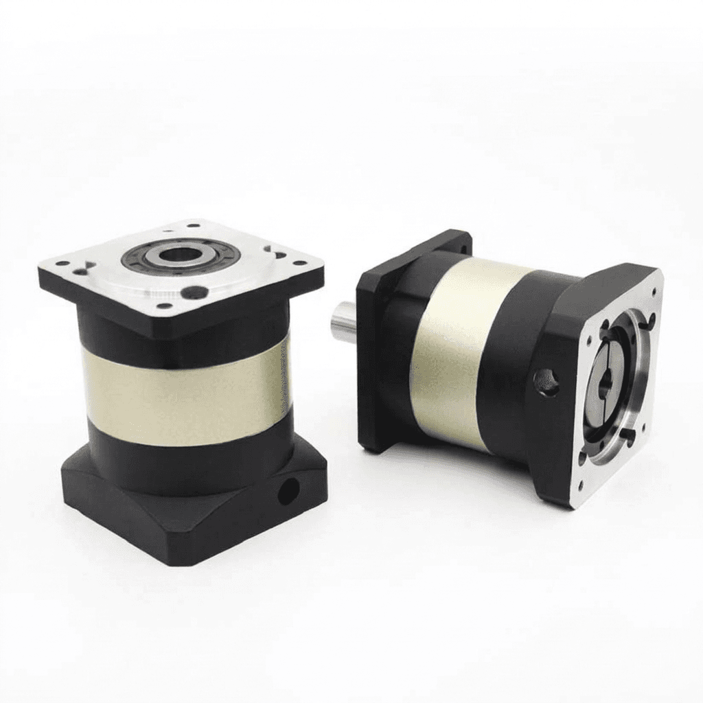
Input Clamping Hub vs. Keyway in Servo Planetary Gearheads: Preventing Fretting Corrosion, Micro-Slippage, and Dynamic Backlash Growth
Compare input clamping hub vs keyway connections in servo planetary gearheads. Check fretting risks, torque margins and motor fit with a supplier RFQ checklist.
One-line decision — input clamping hub vs keyway: For precision reversing servo axes, favor a manufacturer-approved friction clamp to avoid key-flank clearance. Select by verified torque, fit and duty cycle. A keyed motor can be compatible with a clamp, but key removal, half-key use and slot orientation require the exact assembly instructions.
Scope and engineering limits: This Global, English-language guide supports machine designers, robotics integrators and buyers pairing servomotors with precision planetary gearheads. Published and reviewed: 02 November 2026 (UTC). It compares mechanisms and supplies an RFQ/acceptance method; it reports no physical endurance tests or customer failure statistics. Worked examples are illustrative. Final fit, torque, speed and assembly limits come from the selected manufacturers.
Fast action path: Review our inline planetary gearhead product catalog, or request an application engineering motor-matching review by submitting your motor dimension drawing and peak dynamic duty cycle.
Executive Summary: The Hidden Failure Point in Servo Drivetrains
Consider an illustrative diagnostic scenario, not a reported customer case: a reversing pick-and-place axis develops positioning errors despite a low-backlash gearhead specification. The team initially suspects internal gear wear.
Inspection should also cover the motor shaft, input hub and sleeve. Red-brown or black debris can indicate fretting corrosion, while loose fasteners, damaged fits and other drivetrain clearances are alternative causes. Measure the interface before attributing all lost motion to the gears. A linear clearance cannot be converted to angular play without its contact radius.
Loaded interface + relative micro-motion
                  ↓
Wear debris + oxidation → possible fretting damage
                  ↓
Inspect fit and preload; measure input lost motion
                  ↓
Refer input play to output using the reduction ratio
Connecting a servomotor to a planetary gearhead requires transmitting acceleration and braking torque through a compact interface. Parallel keys and friction clamps can both transmit torque; a clamp offers a useful route to avoiding geometric reversal clearance. Its performance still depends on contact conditions, dimensions and assembly.
1. Mechanics of Torque Transmission: Form-Fit vs. Friction-Fit
To evaluate the input interface, engineering teams must contrast the physical mechanisms governing force transfer: positive mechanical form-locking versus uniform frictional surface pressure.
Parallel Keys: Flank Contact and Geometric Notch Effects
Traditional keyed connections transfer torque via direct contact pressure along the side flank of a rectangular feather key seated in a shaft groove.
- Clearance and reversal: Torque acts through the key flanks. If the specified fit leaves flank clearance, a torque reversal can traverse that gap before the opposite flank carries load. Key dimensions alone do not establish the clearance of an assembled joint.
- Notch effects: A keyway changes the shaft section and local stress distribution. The stress concentration depends on groove geometry and loading; a single universal notch factor cannot establish torsional or bending fatigue strength. Check the motor supplier's shaft-load limits.
- Balance: Assess the assembled motor, key, hub and sleeve at the intended speed. A balance key is part of a specified balancing arrangement, not an automatic cure for runout or insufficient torque capacity.
Friction Clamping Hubs: Distributed Radial Contact Pressure
A friction clamping system uses a split or collet hub tightened by the specified fasteners. Bolt property class, thread condition and installation torque belong to that hub's assembly specification.
- Contact pressure: Tightening produces radial contact pressure. Real pressure varies near slots, edges and a shaft keyway; the schematic below uses idealized arrows.
- Reversal behavior: Within its approved friction capacity, the joint can transmit reversal torque without taking up key-flank clearance. Elastic twist and local micro-motion remain possible; a backlash-free connection does not mean infinite stiffness.
- Shaft condition: A smooth shaft avoids the keyway notch, but surface damage, shoulders and other features still affect strength. Removing a key does not remove the shaft's keyway.
The diagram below contrasts distributed clamping with key-flank loading. It is an explanatory schematic, not a stress simulation or a measured pressure map.
2. Tribology and Failure Modes: Fretting and Lost Motion
Tribo-Oxidation (Fretting Corrosion)
Small relative movements at a loaded metal interface can detach particles that oxidize. Debris and damaged contact surfaces can then change the fit and load distribution. SKF describes this mechanism for bearing rings and their seats, including red or black corrosion products, in Bearing Damage and Failure Analysis, printed page 51.
Applying that mechanism to a servo input is an engineering inference, not a gearhead endurance result. Neither a universal micro-motion amplitude nor a fixed time to failure follows from it. A poorly assembled friction clamp can also fret. Inspect shaft and bore condition, engagement length, fit and retained clamping force.
Do not transfer a bearing-seat recommendation for anti-fretting paste to a dry-spec torque clamp: changing the surface condition changes its friction capacity. Follow the selected clamp's cleaning and lubrication instructions.
Dynamic Backlash Growth: Refer Input Play to the Correct Shaft
Input angular clearance contributes approximately the following output lost motion, with all angles expressed in the same unit:
Additional output play = input angular play / i
where i = input speed / output speed (> 1 for a reducer)
Illustrative calculation: If measured input play is 15 arcmin and the reduction ratio is 10:1, its output contribution is 1.5 arcmin, not 150 arcmin. Adding that to a separately measured 3 arcmin gear-mesh value gives a simple worst-case allowance of 4.5 arcmin, only if both values use compatible load and measurement conditions. This is arithmetic, not a prediction of wear or a product rating.
Clearance and elastic twist can both affect servo response. Hunting or positioning error alone does not identify the failed component. The motor encoder cannot directly measure output position while an input joint moves relative to the shaft.
Separate Interface Wear from Gear-Mesh Backlash
Record a baseline reversal test at commissioning. For a later comparison, use the same test torque, temperature, holding arrangement, instruments and measurement location. Measure the motor-to-input joint separately where the manufacturer permits, then assess the gearhead under its specified backlash method. Do not compare unloaded motor-encoder motion with a loaded output-backlash specification.
A keyway also changes local shaft stress. Repeated braking and reversing loads require a geometry-specific fatigue check; neither shaft fracture nor plastic yielding is an inevitable consequence of using a key.
3. Structural Comparison: Input Interface Architectures
The table is a qualitative selection framework. It assigns no universal torque multiplier, cost premium, notch factor or service life. Request ratings for the actual assembly.
| Interface Architecture | Reversal Behavior | Main Fretting / Fit Concern | Required Supplier Evidence | Assembly Consideration | Selection Boundary |
|---|---|---|---|---|---|
| Direct-bore split clamping hub | Avoids key-flank take-up within approved capacity | Insufficient contact pressure, poor fit or contamination | Interface torque, speed and accepted shaft tolerance | Use specified engagement and screw torque | Useful starting point for precision servo axes |
| Two-piece split clamping hub | Can avoid geometric clearance; still twists elastically | Uneven tightening or contact | Rating for the complete collar and fastener arrangement | Follow tightening sequence | Select for the actual space, service and duty requirements |
| Conical locking element | Frictional transmission within rated limits | Incorrect fit or assembly condition | Shaft/hub stress, dimensional and torque limits | May require several bolts and a tightening sequence | Use only where the motor and hub accept its forces and envelope |
| Clamping hub with approved reduction sleeve | Can avoid key-flank clearance | Additional fit interfaces and slot orientation | Rating for the specific hub, sleeve and shaft combination | Fit only the designated sleeve | Useful for a supported motor shaft adaptation |
| Keyed shaft with clamp assist | Depends on whether friction or the key carries reversal torque | Unclear load-sharing and residual clearance | Defined torque path, fit and fatigue assessment | Verify key and clamp arrangement | Do not assume the key increases a clamp's approved capacity |
| Direct keyed bore | Flank clearance may create lost motion | Fit wear and keyway contact stress | Key strength, shaft limits and measured reversal play | Check flank fit and axial retention | Accept only when the motion and durability requirements are met |
4. Practical Engineering: Handling Keyed Servo Motors in Friction Clamping Hubs
A keyed motor shaft and a torque-transmitting keyed input are different arrangements. A clamp may grip a motor shaft whose full key has been removed, if the selected manufacturers permit it. Shaft tolerance follows the motor drawing and hub approval; there is no universal k6 or m6 requirement for every servo input.
Exact motor drawing + exact gearhead adapter
                    ↓
Manufacturer approves shaft / hub / sleeve combination?
       No → request a matched adapter or another motor option
       Yes → follow its key, slot and tightening instructions
                    ↓
Verify torque / speed / duty and record an acceptance baseline
Scenario A: Smooth Shaft
- Check: Diameter and tolerance, usable engagement, shoulder clearance, runout, pilot and bolt pattern.
- Assemble: Clean with a manufacturer-approved agent; protect seals and coatings. Insert without forcing or hammering and follow the mounting and clamp tightening sequence.
- Limit: A smooth shaft does not establish torque capacity, balance quality or freedom from fretting by itself.
Scenario B: Keyed Shaft with Key Removed
- Check: Obtain written approval for clamping onto the remaining shaft surface and the required hub/sleeve orientation.
- Assemble: Remove the full key when instructed. Do not infer a universal slot direction from another gearbox series or substitute a generic contact-area derating.
- Limit: The keyway remains in the shaft. Its effects on contact and strength remain part of the approved design.
Scenario C: Manufacturer-Specified Half or Modified Key
Use a half or modified key only in the specified balancing and coupling arrangement. It does not automatically restore the shaft's fatigue strength or the clamp's full-bore torque rating. Kollmorgen's Essentials shaft-key installation instructions show a model-specific modified key aligned to the rounded shaft surface and require dimensional inspection. That example is not permission to machine an arbitrary key for another motor.
Scenario D: Approved Slotted Reduction Bushing
Use the manufacturer's designated sleeve, length, fit and slot orientation. Avoid improvised shims and obtain the torque rating for the sleeved assembly. APEX's AT-series mounting instruction, pages 1–3 illustrates key removal, a balance key where necessary, bushing arrangements and separate mounting/collar torque tables. Its illustrated orientation and tightening values apply to those listed arrangements; they are not general instructions for every gearhead.
5. Mathematical Sizing: Frictional Torque and Clamping Margin
An ideal cylindrical contact with uniform pressure provides this screening relationship:
T_fric = μ × p × A × (d / 2)
       = (π / 2) × μ × p × d² × L_eff
Here, T_fric is friction torque in N·m; μ is the dimensionless friction coefficient; p is contact pressure in Pa; d and L_eff are shaft diameter and effective contact length in metres; and A = π × d × L_eff. This idealization assumes full cylindrical contact and a known surface condition. Slots, an open keyway, sleeves and nonuniform pressure need a more specific model or supplier validation.
Do not infer contact pressure or an approved transmissible torque from bolt diameter or tightening torque alone. Fastener preload, collar stiffness and contact geometry intervene. Use the supplier's joint rating for the actual fit and assembly condition.
For a preliminary margin comparison:
Required interface rating ≥ agreed margin × peak interface torquePeak interface torque must include the relevant acceleration, braking and transient load cases at the input shaft, including inertia and permitted peak duration. It is distinct from the gearhead's nominal output torque. An application-specific margin also does not replace a fatigue or machine safety assessment.
Illustrative check: With an assumed peak interface torque of 50 N·m and a project-agreed margin of 1.5, the required rating is 75 N·m. A candidate rated at 70 N·m falls short, despite exceeding the bare peak. The margin is an example input, not a universal recommendation. An unknown interface rating leaves the selection unresolved.
Supplier Sizing and Assembly Evidence Matrix
| Required Input | Where to Obtain It | What to Verify Before Approval |
|---|---|---|
| Continuous and peak interface torque | Motor/load duty calculation and supplier rating | Same shaft reference, peak duration and repetition |
| Input speed and balance limits | Motor and gearhead specifications | Permitted speed for the actual key/hub/sleeve assembly |
| Shaft and bore fit | Exact motor drawing and adapter drawing | Diameter, tolerance, surface condition and runout |
| Effective engagement length | Sectioned adapter assembly drawing | Full usable contact without bottoming at the shoulder |
| Key and sleeve arrangement | Model-specific mounting instruction | Approved parts and exact slot orientation |
| Clamping screw installation torque | Hub marking or current assembly manual | Correct fastener, thread condition, torque and sequence |
| Acceptance and follow-up method | Agreed inspection plan | Baseline lost motion, test load, temperature and review interval |
Under-tightening can reduce capacity; over-tightening can damage the joint. Record the manufacturer's specified torque using a calibrated tool. Do not apply an assumed percentage relationship between installation torque and transmitted capacity.
6. Sourcing and Procurement: The 7-Gate Input Compatibility Checklist
Use these checks before releasing the purchase order:
- Gate 1: Exact Motor Drawing — Confirm model, shaft diameter/tolerance, usable length, keyway, pilot and bolt pattern.
- Gate 2: Shaft Profile Approval — Confirm smooth or keyed supply and the manufacturer's key-removal or modified-key instruction, where applicable.
- Gate 3: Matched Adapter — Obtain the motor/gearhead adapter drawing and any designated reduction sleeve, including slot orientation.
- Gate 4: Dynamic Duty — Record torque reversals, acceleration, speed, inertia, cycle timing and braking events. There is no universal reversals-per-minute cutoff that approves or rejects an interface.
- Gate 5: Torque Margin — Compare the complete interface rating with the input torque envelope, permitted peak duration and agreed application margin. Treat missing ratings as unresolved.
- Gate 6: Surface Preparation — Follow the specified cleaning and lubrication condition. Keep oil or anti-fretting paste off a dry-spec torque contact unless expressly approved.
- Gate 7: Assembly and Acceptance Record — Put the specified clamp torque and sequence on the traveler; retain tool calibration and a repeatable lost-motion baseline. Confirm any separate holding-brake requirements for vertical axes.
If any gate remains open, request the missing adapter or interface-rating information with the motor drawing and duty profile before ordering production quantities.
7. Cost-Benefit Analysis: Use a Break-Even Worksheet
Compare actual supplier quotations and your maintenance records. A friction clamp is not evidence of zero failures, and a keyed connection does not establish a predictable failure rate. The worksheet below helps procurement assess the premium without inventing either.
| Cost Input | Evidence to Use | Treatment in the Comparison |
|---|---|---|
| Gearhead / adapter premium | Like-for-like quotations | Per-axis difference × number of axes |
| Motor or shaft-option premium | Motor quotation | Add any smooth-shaft or approved-key cost |
| Assembly and tooling difference | Installation work instruction and labor rate | Include torque-tool verification and actual labor |
| Planned inspection difference | Agreed maintenance schedule | Compare equal operating periods |
| Cost per unplanned event | Service records | Include downtime, parts and labor once each |
| Expected events avoided | Comparable field data or an explicit scenario range | Keep unknown where evidence is absent |
| Net financial effect | Combined worksheet | Avoided event cost minus all incremental costs |
Illustrative arithmetic, not a quotation or reliability forecast: Ten axes at a 60 USD interface premium plus 50 USD total added assembly cost produce a 650 USD incremental cost. If one avoided event would cost 1,500 USD in total, break-even requires more than 650 / 1,500 = 0.433 expected avoided events across the fleet and evaluation period. This simplified example assumes all other cost differences are zero. Without evidence for the expected event reduction, no savings percentage is established.
For related interface and acceptance decisions, see Flange vs. Shaft Output Planetary Gearheads and Backlash vs. Repeatability Acceptance Criteria.
8. Frequently Asked Questions
Why do precision planetary gearheads avoid keyways on the input motor connection?
A friction clamp can avoid key-flank clearance during torque reversal. A keyed connection can still work when its fit, fatigue strength and lost motion meet the application requirements. Neither design is immune to fretting; validate the complete motor-to-gearhead interface.
Can I mount a servo motor with an existing keyway into a friction clamping collet?
Only when the motor and gearhead manufacturers approve that combination. Remove the full key if the clamp instructions require it; use a half or modified key only when specified. Obtain the exact slot-orientation drawing and approved torque capacity rather than applying a universal alignment or derating rule.
What is fretting corrosion, and how does it affect backlash?
Small relative movements at loaded metal contacts can produce wear debris that oxidizes, often leaving red-brown or black deposits. Wear can increase input lost motion. For reduction ratio i, input angular play contributes approximately input play divided by i at the output; measure gearbox backlash separately under a defined test load.
Does a friction clamping hub slip under emergency stop (E-stop) torque peaks?
It can slip if the actual joint capacity is exceeded or assembly conditions differ from the approved specification. Compare the supplier's interface rating with acceleration and braking torque, including duration and repetition. Use the application-specific margin agreed with the supplier; a clamp is not a safety brake.
Are slotted reduction bushings reliable for adapting smaller motor shafts?
A manufacturer-approved sleeve can be suitable when its bore, length, fit, slot orientation and torque rating match the specific motor and hub. Do not substitute improvised shims. Request approval for the complete sleeved assembly rather than assuming it has the direct-bore rating.
How should procurement verify motor shaft compatibility on gearhead RFQs?
Send the exact motor drawing, shaft diameter and tolerance, engagement length, keyway details, pilot and bolt pattern, speed, and continuous, acceleration and braking torque with duty cycle. Ask for a matched adapter drawing, interface torque rating, assembly instructions and an agreed lost-motion acceptance test before releasing the purchase order.
9. Sources and Engineering References
Sources checked 02 November 2026 (UTC). These are primary manufacturer documents. Their scope is identified below; they do not certify this article's examples or endorse PrecisionGearhead products. Obtain the current manual for the exact model being purchased.
- APEX Dynamics — AT-Series Motor Mounting Instruction, APEX.AT.EN.2012.001. Pages 1–3 cover mounting, key/bushing arrangements and model-specific bolt torques. An older manufacturer instruction used to illustrate why assembly values must be matched to the product; not a current cross-brand torque chart.
- Kollmorgen — Essentials Motor Shaft Key Kit: Installation. Steps 6–8 and the half/modified-key table document model-specific key installation and dimensional checks; they do not approve other motor/coupling combinations.
- SKF — Bearing Damage and Failure Analysis. Printed page 51, “Frictional corrosion – Fretting corrosion,” explains micro-movement, oxidation and fit damage at bearing seats. Used for the mechanism only, not a servo-clamp life or torque rating.
10. Next Steps: Secure Your Motor-Gearhead Input Interface
Before issuing a production purchase order, compile the motor drawing, input torque/speed envelope, duty cycle and required output lost-motion limit. Ask for a matched adapter drawing, approved hub/sleeve/key arrangement, interface torque rating and assembly instruction.
Contact PrecisionGearhead Engineering with those documents for a motor-matching inquiry, or explore our inline planetary gearhead series and right-angle planetary gearhead series to discuss a suitable configuration.
Author

Categories
More Posts

Precision Gearhead Update 2026-W25: Inertia Matching & Sourcing Controls
Weekly precision gearhead update: lock rotor-to-load inertia ratio limits, check standards, and freeze motor-to-gearhead flange interface drawings at RFQ.
Backlash vs Repeatability: How to Set Acceptance Criteria Before PO
Buyer-side method to separate backlash and repeatability, lock test protocols, and release PO with measurable acceptance evidence.
Flange vs. Shaft Output Planetary Gearheads: Torsional Stiffness, Space, and Cost Trade-offs
Compare flange vs shaft output planetary gearheads for stiffness, space, and BOM cost. Use the checklist to choose the right OEM servo gearbox.