
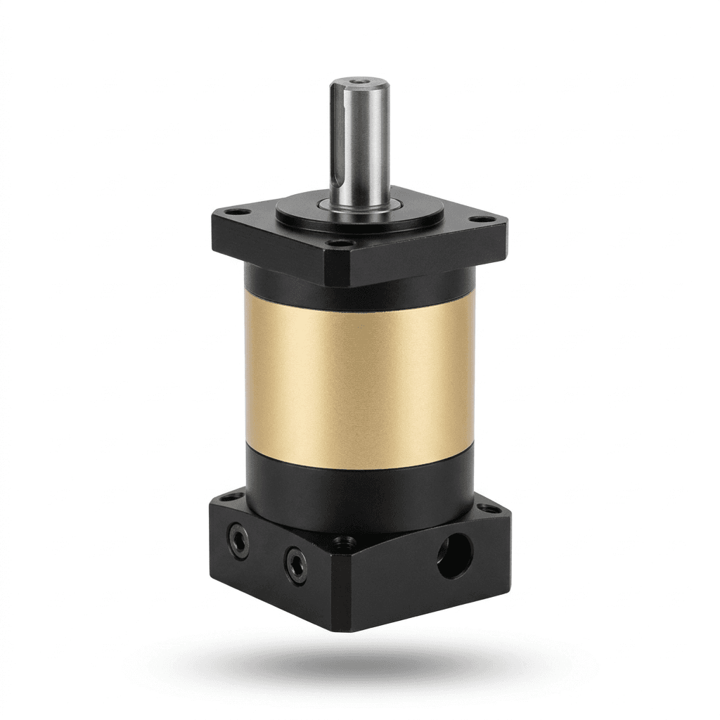
Vertical (Z-Axis) Planetary Gearheads: Gravity Overhauling Loads, Mounting Orientations, Lubricant Migration, and Emergency Brake Sizing
Specify vertical planetary gearheads with gravity-load calculations, brake delay checks, lubrication limits, and an RFQ checklist for engineering review.
One-line decision: Specify vertical planetary gearheads from the complete gravity-load and stopping profile. Confirm load retention, brake delay and dynamic capacity, and the manufacturer's approved mounting and lubrication conditions before selecting a frame size.
Scope and review date: Reviewed 9 November 2026 for automation integrators, machine builders, Cartesian robot designers, and procurement teams worldwide. This is a preliminary engineering and RFQ guide for servo-driven vertical axes, not a certified safety design or a product-specific installation instruction. Numerical examples are calculated scenarios, not measured gearbox or brake tests. Apply the machinery requirements relevant to the installation country and machine type.
Fast action path: Compare precision inline planetary gearheads and request an engineering review with the payload, transmission geometry, motion cycle, and mounting drawing. Ask the supplier to identify the exact model and operating limits supporting its recommendation.
1. Executive Summary: Four Checks for a Vertical Drivetrain
A vertical Z-axis adds a continuous gravitational load to the acceleration and friction loads used for horizontal-axis sizing. The gearhead's physical shaft orientation and the carriage's travel direction are separate questions: a horizontal-shaft reducer can still drive a vertical rack or belt. Document both before comparing quotations.
Four checks determine whether a proposed drivetrain is suitable:
- Load retention: Precision planetary gearheads are normally backdrivable. Tooth friction, a high reduction ratio, or motor cogging must not be treated as a safety holding function. Assess the complete load path, including couplings, belts, screws, and brakes.
- Stopping behavior: A holding brake has a finite torque build-up time and may have limited permission for dynamic stops. Motor torque removal, brake application, and drive regeneration must be evaluated together. Neither the gearbox's peak torque rating nor the brake's static holding rating establishes safe stopping distance.
- Mounting and lubrication: Shaft-up and shaft-down arrangements can change lubricant distribution and seal exposure. The effect depends on the design; an approved all-position gearbox does not automatically need extra fill or derating.
- Duty and heat: Lifting, descending, dwelling under torque, and repeated braking load different parts of the system. Check motor heating, gearbox ratings, and drive energy absorption separately.
The practical purchasing output is a documented load case with supplier limits and unresolved conditions clearly identified. A nominal torque comparison alone is insufficient.
2. Back-Drivability Mechanics: Why Planetary Gearheads Are Not Brakes
High reduction ratios reduce the torque reflected to the motor, but do not establish self-locking. Planetary gear tooth contact includes rolling and sliding, and the reverse behavior depends on speed, load, seals, bearings, and lubricant. Do not derive a guaranteed reverse efficiency from forward efficiency or assume that a worm reducer is a safety brake either.
Conceptual load-path diagram, not a certified brake arrangement. The 350 kg label is an illustrative payload; the figure does not establish an efficiency, response time, or shock multiplier.
Identify the Output-Side Gravity Torque
For an ideal, lossless mechanism, define the effective travel radius r_eff as linear travel per radian at the gearbox output:
- Ball screw:
r_eff = p / (2π), where screw leadpis in metres per revolution. - Rack-and-pinion or belt pulley:
r_effis the pitch radius in metres. - Static gravity torque:
T2,grav = m × g × r_eff, in newton-metres.
Use the total moving mass, including carriage, tooling, workpiece, and any moving services. For 350 kg on a 10 mm lead screw, the ideal output torque is 350 × 9.81 × 0.010 / (2π) = 5.46 Nm. With a 10:1 reducer, the corresponding ideal motor-side torque is 0.546 Nm. This is a geometry calculation, not an approved holding-brake rating.
When estimating moving-load backdrive torque, use separate manufacturer data for the screw and gearhead in the reverse power direction. For example, reverse gearbox torque transfer can be written T1,back = T2,back × ηg,back / i, with reduction ratio i. Static retention should not depend on uncertain friction credits. Confirm brake holding torque at the relevant temperature and wear condition, and check all intervening connections.
A motor-mounted brake cannot retain the carriage after a downstream coupling, belt, or screw failure. If that failure creates a hazard, the risk assessment may require an independent restraint acting closer to the load. A counterbalance can reduce demand but needs its own failure analysis.
3. Emergency Stop: Brake Delay, Drop Distance, and Arrest Torque
An emergency stop does not always mean immediate torque removal. The selected safety function and fault response determine the sequence. Safe Torque Off (STO) removes torque-producing capability; it does not mechanically hold a hanging load. A controlled stop may retain motor torque during deceleration and brake engagement when the drive remains available. A complete power loss needs separate treatment.
Kollmorgen's AKD2G brake-timing guidance describes the distinction between controlled stopping and immediate drive disable. Its settings are product-specific, not a wiring prescription for other drives.
An Illustrative Delay Calculation
Use the brake's actual engagement data, including controller delay, coil suppression, temperature, air gap, wear, and the time to develop sufficient torque. There is no universal 40–100 ms value for all servo brakes. Changing a diode or suppression device requires manufacturer approval of electrical and switching limits.
For illustration only, suppose a load starts from rest, motor support disappears, and it experiences unconstrained gravity acceleration for an assumed t_delay = 0.070 s:
v_drop = g × t_delay = 9.81 × 0.070 = 0.687 m/s
s_delay = 0.5 × g × t_delay² = 0.0240 m = 24.0 mm
This simplified scenario omits reflected rotary inertia, friction, counterbalance, compliance, residual motor torque, and the brake torque ramp. It is neither a prediction for a connected axis nor a guaranteed worst case. If the axis is already descending, its initial speed adds to both speed and distance during the delay.
Arrest Torque Is a Separate Check
Assume, additionally, constant deceleration from 0.687 m/s to rest over t_arrest = 0.020 s. The assumed upward deceleration is 34.3 m/s². For the same 350 kg mass:
F_arrest = m × (g + a_arrest) ≈ 15,451 N
T2,arrest,ideal = F_arrest × p / (2π) ≈ 24.6 Nm
s_arrest = 0.5 × v_drop × t_arrest ≈ 6.9 mm
Total illustrated descent = s_delay + s_arrest ≈ 30.9 mm
The force is approximately 4.5 times static weight because of these assumed times. It is not a general 3–5 times nominal-gearbox-torque rule. A 1,200 kg rack-driven load with a 31.8 mm pitch radius under the same assumed deceleration would produce about 1,685 Nm at the output in this ideal model. Different geometry changes the required torque substantially.
Actual peak torque requires the mechanism's inertia, efficiencies in the correct power direction, elasticity, backlash, and measured or validated brake response. The assumed arrest time must be checked against available dynamic brake torque; it cannot be chosen independently to make the result fit a catalog rating. Shorter stopping distance can demand a larger peak torque.
Verify Both Torque and Energy
Compare the validated gearbox output peak against the manufacturer's emergency-stop rating, sometimes labeled T2NOT. Obtain its permitted duration, speed, repetition count, and life restrictions. A rating exceedance means the application is outside the stated limit; it is not a known fracture threshold. The references here do not establish a universal ISO-mandated 1.5 or 2.0 torque multiplier.
Separately verify the brake's dynamic torque, kinetic-energy capacity, gravitational work during descent, allowable stopping speed, and permitted emergency-stop count. Include reflected rotary kinetic energy. A static holding rating does not approve repeated service braking. Beckhoff's AM8100 holding-brake instructions illustrate why emergency-stop limits and personnel-protection restrictions must be checked for the exact motor and brake.
4. Mounting Orientations: Shaft-Up, Shaft-Down, and Horizontal
Describe orientation in plain language and include an installation drawing. Some flange-motor conventions use V1 for shaft-down, V3 for shaft-up, and B5 for a horizontal arrangement, but do not assume those labels identify every gearbox manufacturer's mounting option. Confirm the code against its own drawing.
Conceptual lubricant-distribution checks. The shaded areas do not specify a fill level, and the diagram does not imply that an approved vertical installation will suffer starvation or leakage.
Shaft-Down: Check the Lower Output Seal
With the output pointing toward the floor, lubricant may collect near the output bearings and seal. Ask about seal compatibility, permitted temperature and shaft speed, external contamination, and leakage inspection access. Internal pressure depends on lubricant, fill, temperature, and venting; a generic pressure estimate is not a seal specification.
If the axis operates above a product or clean process, define acceptable leakage and the containment or inspection method. An ingress-protection rating alone does not prove lubricant retention or hygiene suitability. FKM is not automatically superior for every fluid and temperature, and a labyrinth is not inherently a static liquid barrier.
Shaft-Up: Check Upper Bearing Supply and Ingress
With the output pointing upward, confirm how the upper bearings and gear stages receive lubricant after long standstill and during the intended speed cycle. Grease rheology, internal passages, bearing sealing, and factory fill all affect the answer. Also examine whether cleaning liquid or condensation can collect around the exposed shaft interface.
Vertical suitability is model-specific. Neugart's May 2025 gearbox catalog, printed page 15, describes all-position operation without performance loss for its gearbox range. This contradicts a blanket vertical derating rule; it does not approve another manufacturer's model or every process condition. Do not add lubricant or install baffles without the supplier's instruction: excessive fill can increase churning and heat.
5. Architectural Comparison: Vertical vs. Horizontal Mounting
Use this matrix to request evidence rather than prescribe a universal seal, fill quantity, or thermal factor. The mounting columns describe the gearbox shaft, while gravity-loading risk follows the driven carriage's travel direction.
| Sizing and sourcing parameter | Horizontal shaft | Vertical shaft-down | Vertical shaft-up | Procurement action |
|---|---|---|---|---|
| Lubricant distribution | Confirm normal duty approval | Check upper-stage supply | Check upper-bearing supply | Request exact model installation limits. |
| Output seal exposure | Depends on housing and fill | May contact pooled lubricant | May face pooled external liquid | Specify fluid, washdown, and leakage criteria. |
| Thermal capacity | Depends on speed, load, and mounting | No universal derating percentage | No universal derating percentage | Obtain the approved duty and temperature calculation. |
| Backdrive load | Can still drive a vertical carriage | Depends on driven mechanism | Depends on driven mechanism | Provide the load-path and travel-direction drawing. |
| Emergency-stop peak | Includes inertia and external forces | Include gravity if carriage is vertical | Include gravity if carriage is vertical | Check torque, duration, energy, and stop count. |
| Motor adapter interface | Check fit and seal arrangement | Motor commonly above gearbox | Motor commonly below gearbox | Confirm mounting support and shaft sealing. |
| Backlash and compliance | Affect reversal accuracy | Gravity may maintain one loaded flank | Gravity may maintain one loaded flank | Evaluate torque sign changes, not just motion reversal. |
| Acceptance evidence | Duty and installation approval | Orientation approval and leakage checks | Orientation approval and bearing supply | Record supplier assumptions before the purchase order. |
6. Four-Quadrant Torque Profile and Gravity Overhauling
Use one sign convention throughout: upward travel, upward drive force, and their corresponding output rotation are positive. For an ideal transmission, no counterbalance, moving mass m, and friction magnitude Ff opposing motion:
F_drive = m × (g + a) + Ff × sign(v)
T2,ideal = F_drive × r_eff
P2 = T2 × ω2
Here a is signed vertical acceleration, v is vertical velocity, and ω2 is output angular speed. At standstill, use an appropriate static-friction model rather than assigning a velocity sign. Add rotary inertia and real mechanism losses separately. A counterbalance subtracts its signed upward support force, with allowance for stroke dependence and failure cases.
| Motion phase | Signs under the convention | Ideal drive force | Engineering interpretation |
|---|---|---|---|
| Lifting acceleration | Positive velocity and acceleration | m(g + a) + Ff | Gravity and acceleration both increase demand. |
| Constant-speed lifting | Positive velocity; zero acceleration | mg + Ff | Positive mechanical power supplied to the load. |
| Lifting deceleration | Positive velocity; negative acceleration | m(g + a) + Ff | Torque may stay positive or cross zero. |
| Lowering acceleration | Negative velocity and acceleration | m(g + a) − Ff | Acceleration magnitude determines torque sign. |
| Constant-speed lowering | Negative velocity; zero acceleration | mg − Ff | Regeneration is possible when gravity exceeds friction. |
| Lowering deceleration | Negative velocity; positive acceleration | m(g + a) − Ff | Upward braking force includes gravity and deceleration. |
| Uncontrolled descent arrest | Depends on speed and brake response | Use a validated transient model | Check both brake capacity and drivetrain peaks. |
A reversal of velocity does not automatically reverse tooth loading: gravity may keep torque positive through both travel directions. Conversely, high acceleration or counterbalance can change the loaded flank. Check backlash and torsional compliance against positioning tolerance rather than assuming a specific arc-minute class prevents all drop.
RMS Torque and Gearbox Life Are Different Calculations
For piecewise-constant torque segments, the mathematical RMS value is:
T_RMS = sqrt(Σ(Tj² × tj) / Σtj)Include all relevant segments, including holding dwells. For motor heating, evaluate motor-side torque/current and the motor's cooling and drive limits. Mechanical output power can be zero at a dwell while motor current still creates heat.
A cubic equivalent torque used in some gearbox life methods is not RMS. Apply the gearhead manufacturer's prescribed load spectrum calculation, including speed weighting and duty restrictions where required. Also check peak torque, input speed, bearing axial/radial loads, and thermal limits. Do not infer a universal service life or combine invented mounting and duty factors with a nominal rating.
During lowering, verify the drive's regenerative path and braking resistor or shared-bus capacity. Include gravitational energy and cycle frequency; gearbox selection alone does not establish the drive's ability to absorb descending-load energy.
7. Counterbalance Strategies: Mechanical, Pneumatic, and Unassisted
A counterbalance may reduce continuous motor torque and stored drop energy, but there is no universal payload threshold at which it becomes mandatory. Compare the full cycle, space, maintenance, and failure response. Do not treat ordinary pneumatic pressure or a gas spring as an independently validated safety restraint.
| Counterbalance method | Potential benefit | Failure and sizing questions | Purchasing evidence |
|---|---|---|---|
| Unassisted drivetrain | Simple mechanism and fewer components | Full gravity demand; separate load-retention design | Motor thermal calculation and validated brake arrangement. |
| Pneumatic cylinder and reservoir | Adjustable support force | Pressure loss, seal friction, hose failure, stroke variation | Force envelope and defined loss-of-pressure behavior. |
| Gas spring | Compact self-contained support | Force changes with stroke, temperature, and age | Supplier force curve, life limits, and inspection method. |
| Counterweight with cable or chain | Can offset static gravity demand | Added moving inertia, travel space, suspension failure | Inertia calculation and inspection/retention plan. |
Before requesting a quotation, record the minimum and maximum counterbalance force over stroke, expected service variation, and the force remaining after a fault. Size the drivetrain and retention measures for the relevant degraded conditions as well as normal operation.
8. Sourcing and RFQ Engineering Checklist for Vertical Z-Axes
Use these eight gates to make supplier responses comparable. An unknown item stays open; a catalog maximum does not close a missing application check.
- Gate 1: Load and layout — Record total moving mass, payload variation, screw lead or pitch radius, stroke, counterbalance, and a drawing showing output-shaft and carriage-travel directions. Confirm the supplier's mounting code.
- Gate 2: Lubrication approval — Obtain written confirmation of the exact model, lubricant, factory fill, standstill conditions, and approved orientation. Make any requested modification subject to supplier instructions.
- Gate 3: Sealing and environment — Specify cleaning fluids, ambient temperature, contamination, leakage acceptance, and inspection access. Ask for compatible seals and process suitability without assuming an elastomer or IP rating proves them.
- Gate 4: Brake and peak load — Supply initial speed, brake torque build-up data, stopping sequence, estimated drop, and validated dynamic torque. Obtain gearhead emergency-stop duration and stop-count limits plus the brake's separate energy and speed approval.
- Gate 5: Complete duty cycle — Include lifting, lowering, acceleration, dwell, and cycle frequency. Request motor heating, gearbox thermal and life checks, and drive regeneration capacity at the stated ambient and mounting conditions.
- Gate 6: Accuracy and interfaces — Agree backlash, torsional stiffness, connection torque capacity, bearing loads, and acceptable positional movement. Check motor mass, support, and adapter loads against the actual layout in either orientation.
- Gate 7: Safety responsibility — Have the machine integrator define the required safety functions and performance level from the risk assessment. Evaluate Safe Brake Control, brake testing, diagnostics, and independent restraints where required; a named drive feature alone does not demonstrate compliance.
- Gate 8: Acceptance record — Agree controlled commissioning checks for retention, fault response, worst-case stopping clearance, leakage, and temperature. Record test conditions, supplier approvals, maintenance intervals, and ownership of unresolved items.
Use ISO 12100's risk-assessment framework to organize hazards and risk reduction, alongside the applicable control-system and machine-specific requirements. It does not replace application calculations or establish the numerical brake margins in this article. Reassess the design if payload, speed, brake model, or counterbalance changes.
If a quotation omits these inputs, send the checklist with your application data and request a revised recommendation. This helps engineering and procurement resolve assumptions before prototype ordering.
9. Frequently Asked Questions
Are precision planetary gearheads self-locking on vertical axes?
Do not credit a precision planetary gearhead with self-locking unless the manufacturer explicitly approves that function. Specify load retention from the machine risk assessment; a motor holding brake alone may not provide personnel protection.
Why can a vertical Z-axis drop during an emergency stop?
Motor support torque can disappear before the brake develops sufficient torque. Drop depends on initial speed, brake delay, reflected inertia, friction, and counterbalance. A controlled stop and coordinated brake sequence can reduce movement when the required drive functions remain available.
How do shaft-up and shaft-down mounting affect lubrication?
Shaft-down mounting can expose the lower output seal to pooled lubricant; shaft-up mounting requires confirmation of lubricant supply to upper bearings. These are design checks, not inevitable failures. Some planetary gearheads are approved for every mounting position without performance derating.
How does gravity affect lifting and lowering torque?
With upward motion defined as positive, gravity always acts downward. Lifting generally requires positive mechanical power. A descending load can drive the motor as a generator when gravity exceeds friction and counterbalance. Torque sign depends on acceleration as well as direction.
What safety factor is required for emergency-stop torque?
There is no universal 1.5 or 2.0 multiplier established by the references in this guide. Obtain the manufacturer-approved peak torque, duration, speed, and permissible stop count, then agree the application margin through the machine risk assessment and sizing review.
Can I mount any catalog planetary gearhead vertically?
Use the exact model installation manual and approved mounting drawing. Confirm lubricant type, fill, temperature limits, duty, and sealing. Do not automatically add lubricant, specify FKM seals, or apply a fixed thermal derating percentage.
How can I reduce drop if the holding brake is slow?
Coordinate motor torque and brake engagement using the drive and brake manufacturers' approved sequence. Assess power-loss and fault cases separately. Where required, use an appropriately rated independent load-side brake or restraint, and validate stopping distance under controlled commissioning conditions.
10. Sources and References for Verification
Sources reviewed 9 November 2026. Manufacturer guidance applies to the products it identifies; the calculations above are illustrative mechanics, not supplier test results or certification evidence.
- Neugart, Complete Gearbox Catalog, May 2025, printed page 15, “Our gearbox features.” Supports the stated all-position capability for that range and the need to avoid blanket derating assumptions.
- Kollmorgen, AKD2G Controlled Stop and Holding Brake Timing, 18 August 2023. Product-specific guidance on controlled stopping, STO behavior, timing, and potential brake damage during engagement at speed.
- Beckhoff, AM8100 Holding Brake. Product-specific restrictions on service braking, emergency stops, and reliance on a holding brake for protection of people. Its numeric limits must not be transferred to another brake.
- ISO 12100:2010, Safety of machinery — General principles for design — Risk assessment and risk reduction. The official catalog explains its scope and risk-assessment methodology; it is not evidence of machine certification or a universal torque safety factor.
11. Next Steps: Specify a Reviewable Vertical Drivetrain
Before releasing a purchase order, assemble the gravity-load calculation, complete motion profile, mounting drawing, and brake operating data. Ask for separate confirmation of gearbox peak-load capability, brake stopping capacity, and the approved lubrication arrangement. Keep any unresolved condition visible in the RFQ rather than replacing it with an assumed safety factor.
Compare inline planetary gearhead options or contact the engineering team with those inputs to request model selection and availability confirmation. The machine integrator remains responsible for the safety design and acceptance validation of the complete vertical axis.
Author

Categories
More Posts
Cleanroom and Vacuum Planetary Gearheads: Outgassing, PFPE Lubrication, Particle Emission Classes, and Semiconductor Sourcing
Select cleanroom and vacuum planetary gearheads with outgassing evidence, PFPE lubrication limits, particle testing, and a semiconductor RFQ checklist.

Planetary vs. Strain Wave Gearheads in Cobots: The Cost and Stiffness Trade-off
A procurement and engineering guide comparing strain wave (harmonic) gears to precision planetary gearheads for collaborative robot (cobot) joints in 2026.
Rack and Pinion Planetary Gearheads: Cantilevered Sizing, Radial Moments, and Backlash Preload for Gantry Axes
Size rack and pinion planetary gearheads for gantries. Compare bearing loads, pinion supports, and backlash preload; prepare an RFQ with our checklist.