1. Decide what the calculator can establish
Evidence reviewed . This is a preliminary operating-point guide for a 15:1 gearhead with a 10mm output shaft. No selected product or empirical test record is attached.
Speed is immediately calculable
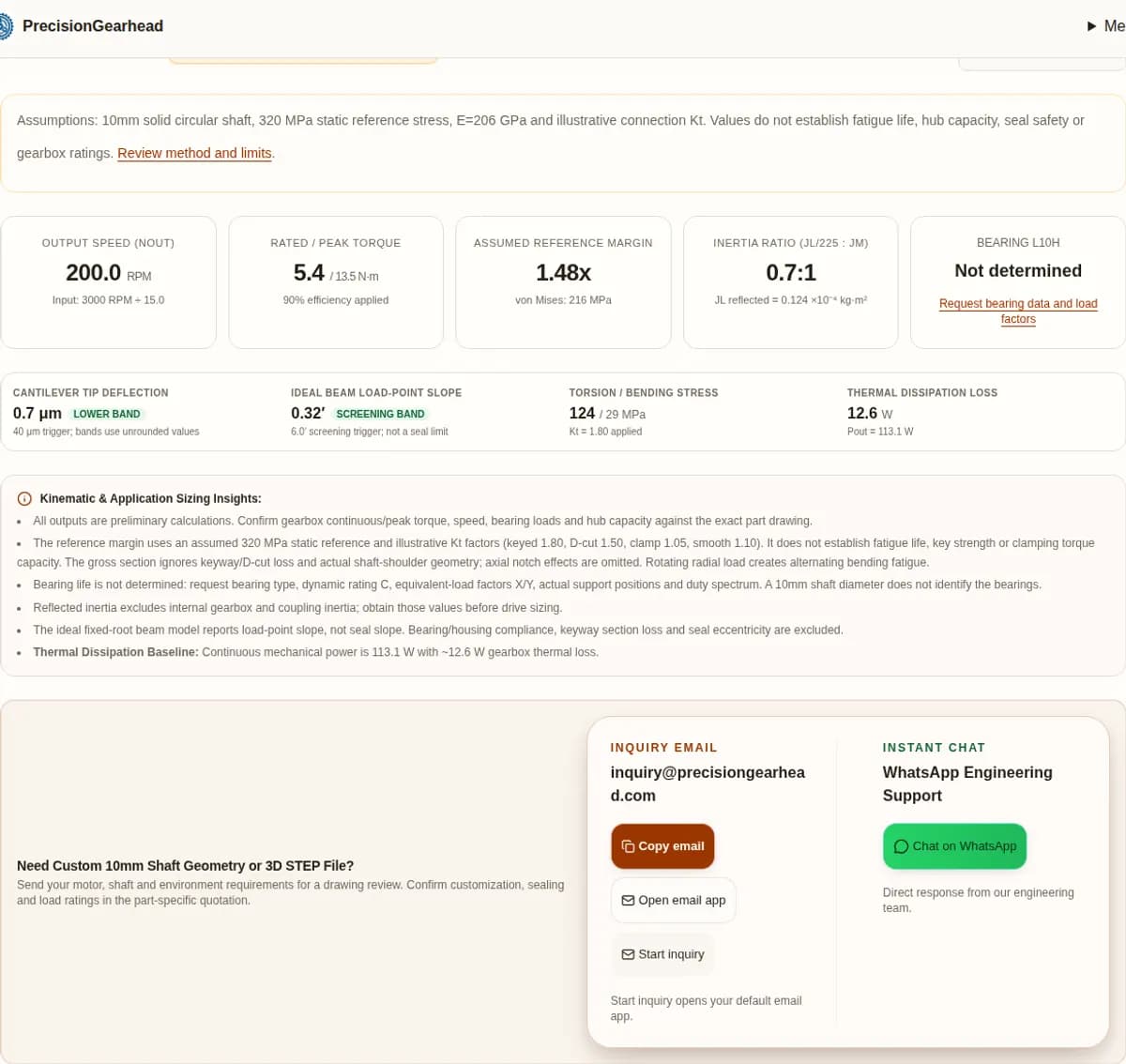
3000 RPM produces 200 RPM at an exact 15:1 ratio. Check absolute ratio where positioning accuracy matters.
Torque is an operating estimate
0.40 N·m × 15 × 0.90 = 5.40 N·m, with 13.50 N·m at a 2.5× motor peak. Neither number is a gearbox capacity.
Inertia is reduced by 225
The squared-ratio relationship reduces motor-side load inertia, while control stability still depends on the complete axis.
A 10mm shaft does not define load capacity
Material, hub, bearings, support geometry and duty must be checked. Bearing life, backlash and frame compatibility remain unverified.
These arithmetic conclusions follow the methods below. The inertia relationship is supported by Oriental Motor’s gearing guidance; the need for part-specific geometry is illustrated by the maxon GP 42 C catalog drawing.
2. Reproduce the method and assumptions
| Quantity | Formula / model | Boundary |
|---|---|---|
| Output speed | n_out = n_in / 15 | Exact only for i = 15; use actual catalog ratio. |
| Output torque | T_out = T_motor × 15 × η | η = 0.90 planetary or 0.78 parallel is an assumption, not a technology-wide rating. |
| Reflected load inertia | J_ref = JL / 225; R = J_ref / Jm | All inertia inputs use ×10⁻⁴ kg·m². Gearbox/input-coupling inertia is excluded. |
| Nominal torsion | τ = Kt × 16T_peak / (πd³) | T in N·mm; d = 10mm; illustrative Kt varies with the connection. |
| Bending and axial stress | σb = Kt × 32FrL / (πd³); σa = Fa / A | L in mm; A = πd²/4. Same assumed Kt applied to bending and torsion. Actual axial and bending/torsion notch factors and shoulder geometry require separate analysis; this is not a conservative bound. |
| Static reference comparison | σvm = √((σb + σa)² + 3τ²); margin = 320 / σvm | 320 MPa is an assumed reference, not certified material yield or endurance strength. No fatigue approval. |
| Ideal beam displacement | δ = FrL³ / (3EI); θ = FrL² / (2EI) | I = πd⁴/64; E = 206000 N/mm². θ is at the load point. A rigid restraint is assumed. |
| Mechanical heat loss | P_out = T_out × 2πn_out / 60; P_loss = P_out × (1/η − 1) | Watts; excludes the motor electrical losses. Do not add separate mesh/seal losses to an efficiency already including them. |
The shaft model uses a solid circular section and illustrative concentration factors: keyed 1.80, D-cut 1.50, clamp 1.05, smooth 1.10. They are teaching assumptions, not values established by DIN 6885. The model does not resolve actual keyway section loss, local contact stress or bending/torsion fatigue factors.
| Measure | Illustrative bands | Use of the result |
|---|---|---|
| Static reference margin | ≥2; 1.4–2; 1–1.4; <1 | Prioritize stress review. No band certifies safety or fatigue life. |
| Ideal beam displacement / slope | 15 μm / 3.5 arcmin; 40 μm / 6 arcmin | Review triggers only. These are not DIN seal acceptance limits. |
| Reflected inertia ratio | ≤3; 3–10; 10–20; >20 | Discussion bands for drive tuning, not universal stability limits. |
| Input speed | >4000 RPM review trigger | Actual continuous/intermittent limits come from the selected gearbox. |
| Bearing life / frame / backlash | Unknown | Request part-specific catalog data. No rating is inferred from shaft diameter. |
3. Read the mechanical relationships
A 3 × 5 stage split is one possible arrangement. This page does not rank internal stage allocations without tooth and carrier geometry.
The result must be compared with the selected gearbox and hub ratings. Power conservation limits torque multiplication at the output speed.
For Jm = 0.18 in the same ×10⁻⁴ kg·m² units, the reflected load/motor ratio is 0.691:1. Gearbox inertia still needs to be added.
In the ideal fixed-root beam, bending moment doubles and load-point slope increases fourfold. Actual bearing support flexibility changes displacement.
4. Compare installation choices before selecting a model
| Choice | Useful when | Required confirmation / tradeoff |
|---|---|---|
| Inline planetary | A coaxial motor/output package suits the machine envelope. | Exact ratio, stages, efficiency, backlash, output shaft and combined-load ratings. |
| Parallel shaft | An offset shaft or alternative package is useful. | Housing geometry, gear material and duty-specific efficiency; do not assume one fixed efficiency for all designs. |
| Keyed hub | A positive mechanical drive is required. | Key dimensions, engagement, bearing pressure and reversing fatigue. Keyway adds local stress. |
| Clamping hub | Adjustable angular orientation and reduced keyway stress are useful. | Slip torque, preload procedure, surface condition and shaft/bore fit. May increase hub cost or length. |
| D-cut / set screw | Simple orientation and compact assembly are priorities. | Set-screw retention, flat geometry and repeatability under reversal. |
| Larger shaft / external support | The 10mm arrangement fails load or stiffness review. | Larger package and adapter cost; avoid misaligned or overconstrained external bearings. |
| Item | Status on this page | Minimum evidence needed |
|---|---|---|
| Ratio and nominal output shaft | Target: exact 15:1 and Ø10mm | Drawing showing absolute ratio, output geometry and tolerances. |
| Efficiency and material | Assumed, not tested | Duty-specific efficiency and material / heat-treatment specification. |
| Bearing fatigue life | Unknown; no C or X/Y values supplied | Bearing selection, support reactions, lubrication and load spectrum. |
| Backlash / lost motion | Unknown | Measurement method, test torque and temperature. |
| Motor frame and flange | Not selected | Pilot, bolt pattern, motor shaft connection and assembly drawing. |
| Price and lead time | Not quoted | Quantity, custom geometry, inspection scope and supplier quotation. |
5. Resolve six practical risks
| Risk | Why the tool is insufficient | Next action |
|---|---|---|
| Reversing shaft fatigue | Static reference margin does not model stress amplitude or mean stress. | Supply duty spectrum, material certificate and notch geometry for fatigue assessment. |
| Belt / pinion bearing overload | Pretension, load position and internal support span affect bearing reactions. | Shorten overhang where practical; have the supplier assess combined loads and any external support alignment. |
| Hub slip or key damage | A lower assumed Kt is not a hub torque rating. | Check engagement length, key bearing stress or specified clamp preload and slip torque. |
| Seal leakage and heating | Load-point slope cannot establish seal eccentricity or temperature. | Check seal-position runout and perform an installation-specific thermal/duty test. |
| Servo oscillation | Low reflected inertia does not establish torsional stiffness or damping. | Include gearbox inertia, backlash and compliance; tune and test the complete axis. |
| Cost and scenario mismatch | A larger motor can raise peak torque beyond the gearbox rating; custom shafts add tooling and assembly cost. | Quote the complete axis, adapter, support, inspection and prototype validation before freezing geometry. |
6. Separate heat-loss arithmetic from temperature validation
At the default 3000 RPM and 0.40 N·m motor torque, mechanical input power is 125.66 W. With assumed η = 0.90, output is 113.10 W and gearbox loss is 12.57 W. Electrical motor power is a different quantity.
A temperature estimate needs measured thermal resistance, ambient conditions and the mounting heat path. No universal 2.5 K/W housing value, 4000 RPM ceiling or lubricant lifetime is established here. Obtain lubrication, orientation, speed and seal requirements from the selected gearbox supplier, then log temperature through the actual duty cycle.
7. Reproduce four hypothetical operating points
These are calculation examples, not field deployments. Use the matching preset in the calculator. All use assumed planetary efficiency 90%; compare force, length and peak torque before accepting the operating point.
NEMA 23 Precision Servo Actuator
Inputs: 3000 RPM, 0.40 N·m, peak ×2.5; Fr = 130 N at L = 12 mm; Fa = 35 N.
- Output RPM
- 200.0
- Rated / peak N·m
- 5.40 / 13.50
- Reference margin
- 1.48× (assumed)
- Beam displacement
- 0.7 μm
Next: Check actual motor flange, shaft fatigue, bearing loads and drive settling performance. No bearing lifetime is predicted.
Try this preset in the calculatorBLDC 24V Roller Conveyor Drive
Inputs: 2400 RPM, 0.30 N·m, peak ×1.8; Fr = 160 N at L = 14 mm; Fa = 20 N.
- Output RPM
- 160.0
- Rated / peak N·m
- 4.05 / 7.29
- Reference margin
- 3.12× (assumed)
- Beam displacement
- 1.4 μm
Next: Confirm D-cut hub retention and continuous bearing/thermal ratings. No bearing lifetime is predicted.
Try this preset in the calculatorHigh-Speed Packaging Indexing Pusher
Inputs: 3600 RPM, 0.50 N·m, peak ×3.0; Fr = 90 N at L = 10 mm; Fa = 50 N.
- Output RPM
- 240.0
- Rated / peak N·m
- 6.75 / 20.25
- Reference margin
- 1.70× (assumed)
- Beam displacement
- 0.3 μm
Next: Confirm acceleration duty, clamp slip torque and reversing fatigue before motion testing. No bearing lifetime is predicted.
Try this preset in the calculatorHeavy Pre-Tensioned Timing Belt Drive
Inputs: 2800 RPM, 0.45 N·m, peak ×2.0; Fr = 320 N at L = 20 mm; Fa = 30 N.
- Output RPM
- 186.7
- Rated / peak N·m
- 6.08 / 12.15
- Reference margin
- 1.42× (assumed)
- Beam displacement
- 8.4 μm
Next: Review resultant belt pull, overhang and combined bearing loads; consider a shorter hub or separately aligned support. No bearing lifetime is predicted.
Try this preset in the calculator8. Translate angular play into application error
Arc displacement is s = rθ, with θ in radians. The table is a geometric conversion at r = 50mm, not a product specification. Backlash, compliance and repeatability must be assessed separately under the same measurement conditions.
| Angular play | Arc displacement | Interpretation |
|---|---|---|
| 5 arcmin | 0.073 mm | Geometric arc only; excludes compliance, runout and controller error. |
| 8 arcmin | 0.116 mm | Geometric arc only; excludes compliance, runout and controller error. |
| 12 arcmin | 0.175 mm | Geometric arc only; excludes compliance, runout and controller error. |
| 20 arcmin | 0.291 mm | Geometric arc only; excludes compliance, runout and controller error. |
9. Questions that affect the selection decision
Ratio and operating point
Does every 15:1 gearhead use two stages?
No. Stage count and ratio allocation depend on the mechanism. A 3:1 × 5:1 train is an illustrative way to obtain 15:1; it is not a requirement or proof of tooth strength.
What output speed does 3000 RPM produce?
For an exact 15:1 ratio, 3000 / 15 = 200 RPM. A catalog label of 15:1 may be rounded; confirm the absolute ratio for accurate positioning.
Is the calculated output torque a gearbox rating?
No. Motor torque × 15 × assumed efficiency is the transmitted operating-point estimate. Gearbox continuous, intermittent, emergency-stop and hub ratings must all be checked separately.
Can stepper holding torque be entered as running torque?
Use the available torque at the actual motor speed from the speed–torque curve. Holding torque is measured at standstill and can substantially overstate available running torque.
Why is load inertia divided by 225?
Motor-side load inertia is JL / i². At exactly i = 15, i² = 225. This excludes gearbox inertia and does not itself guarantee servo stability or settling time.
Shaft and bearings
What is the continuous torque capacity of a 10mm shaft?
Diameter alone is insufficient. Material, heat treatment, keyway geometry, hub engagement, reversing duty, bearing loads and fatigue requirements determine allowable torque. The tool gives a provisional reference margin, not a certified capacity.
Does a clamping hub always carry more torque than a keyed hub?
No. A clamp can avoid a keyway notch but its slip capacity depends on bolt preload, friction, engagement length and tolerances. Request the hub torque rating and assembly procedure.
How should radial belt load be entered?
Enter the resultant shaft force including belt pretension and transmitted belt forces. Torque divided by pulley radius alone is not generally the full bearing load. Supply the force direction and application point on the drawing.
What does unsupported length L mean?
L is the distance from the assumed fixed restraint to the load center in the simplified beam. The flange face is not necessarily the restraint; bearing positions, compliance and housing flexibility require a separate model.
Why is bearing L10h not determined?
The page has no selected bearing dynamic rating C, support geometry or X/Y equivalent-load factors. With those inputs, use the bearing manufacturer method. L10 is a statistical 90% reliability fatigue measure, not guaranteed machine life.
Does the slope result prove that an oil seal will not leak?
No. It is the ideal beam slope at the load point. Actual seal performance depends on seal position, eccentricity, runout, surface condition, speed, lubrication and temperature. The 6 arcmin band is an illustrative review trigger, not a DIN seal limit.
Which shaft fit should be specified?
Use the selected hub and gearbox drawings to specify shaft and bore tolerances together, including runout and surface requirements. A nominal 10mm diameter or a shaft tolerance alone does not determine the assembled fit.
Dynamics and environment
Is backlash the same as lost motion?
Backlash describes clearance on reversal; measured lost motion may also include elastic compliance. Compare values only with the same test torque, fixture, temperature and method. The calculator does not predict either value.
What linear error does 8 arcmin produce at 50mm radius?
Using s = rθ, 8 × π / (180 × 60) × 50 = approximately 0.116mm of arc displacement. This is not the complete positioning error or repeatability specification.
Is 4000 RPM a universal continuous speed limit?
No. It is an illustrative review trigger in this tool. The actual limit depends on gearbox construction, lubrication, duty and mounting. Check the selected catalog and measure temperature under representative duty.
Can calculated heat loss predict housing temperature?
Not without thermal resistance and installation data. The tool estimates mechanical loss using fixed efficiency; it does not predict case temperature, electrical input power or winding temperature.
Can a 15:1 gearhead hold a vertical load when power is off?
Do not assume the gearhead is self-locking. Assess the overhauling load, holding brake and applicable machine safety requirements with the system designer. Forward efficiency alone cannot determine reverse holding performance.
Procurement
Does a 42mm or NEMA 23 motor guarantee a matching 10mm output shaft?
No. Motor mounting dimensions and gearbox output geometry are separate specifications. Check the pilot, bolt circle, input connection, output shaft and load ratings on the exact assembly drawing.
Are the application presets tested installations?
No. They are reproducible hypothetical inputs for comparing calculation behavior. No fleet hours, failure rates, approvals or field-test results are claimed.
What is needed for a firm quote and delivery date?
Send the motor drawing, exact ratio, output torque and speed profile, radial/axial loads and positions, shaft/hub drawings, environment, duty cycle and quantity. Confirm availability, drawings and lead time in the supplier quotation.
10. Trace the evidence and its limits
Sources checked on 2026-11-11. Manufacturer documents support only the statements scoped below. Calculator assumptions are not manufacturer test results or standards certification.
| Source | Supported conclusion | What it does not establish |
|---|---|---|
| Oriental Motor — 4GN15K specifications | Catalog example: 15:1 ratio, 10mm output and 80mm frame; parallel shaft. | Not a drop-in motor interface or a product supplied by us. Request its drawing and duty-specific ratings; no price or stock promise. |
| Oriental Motor — gearing and load inertia | Motor-side load inertia is reduced by the squared gear ratio. | Settling time, universal inertia-ratio limits or gearbox load capacity. |
| JTEKT — calculation of service life, sections 5-2 and 5-3 | L10 is a 90% reliability fatigue statistic. Equivalent-load calculation depends on bearing and loads. | Service life for an unspecified bearing or a guaranteed machine lifetime. |
| maxon — GP 42 C catalog, page 1 drawing and ratio table | The drawing shows a 12mm output shaft; nominal ratio and absolute ratio are separate catalog entries. | An exact 15:1 / 10mm output match. Motor input shaft diameter must not be confused with output diameter. |
| This page’s shaft/beam model | Reproducible idealized arithmetic in section 2 and the calculator. | Certified 320 MPa material strength, fatigue endurance, seal leakage limits or empirical field performance. |
The basic ball-bearing method is L10h = 10⁶/(60n) × (C/P)³. Its prerequisites are absent in this calculator, so bearing life remains unknown. See JTEKT’s life and equivalent-load method for definitions and applicable conditions.
11. Send a complete RFQ and drawing request
Copy the calculator’s current preliminary operating point, then add the missing selection data below. Keep computed torque separate from the supplier’s allowable ratings.
- Exact ratio and output speed profile; motor model, drawing and running torque curve.
- Continuous, acceleration, braking and emergency-stop torque, with duration and cycles.
- Output shaft diameter, usable length, hub/key/flat geometry and mating bore drawing.
- Radial and axial forces, directions and application points, including belt pretension.
- Motor and load inertia, required backlash/lost-motion method and settling target.
- Duty cycle, ambient temperature, mounting heat path, orientation and lubrication environment.
- Required fatigue/bearing life, inspection criteria, annual quantity and prototype test plan.
Inquiry Email
Start inquiry opens your default email app.
12. Follow the selection sequence
- Calculate output speed and transmitted torque from actual running motor data.
- Compare the operating point with gearbox and hub continuous, peak and braking ratings.
- Confirm shaft material, notch geometry and fatigue duty; review beam displacement assumptions.
- Obtain actual bearing reactions, C and equivalent-load factors before life calculation.
- Check inertia, backlash, compliance, thermal duty and brake requirements for the whole axis.
- Approve the assembly drawing and prototype test results before production release.